Gunsmithing the RAS-12 – Part 1

It’s no secret that I have a penchant for oddball guns, be they paintball marker or firearm.  Seeing a design that’s off the beaten path is always enjoyable, be it for mechanical ingenuity or sheer impractical novelty (though usually a peculiar blend of both).  During a recent visit to my friendly local FFL (always good […]

It’s no secret that I have a penchant for oddball guns, be they paintball marker or firearm.  Seeing a design that’s off the beaten path is always enjoyable, be it for mechanical ingenuity or sheer impractical novelty (though usually a peculiar blend of both).  During a recent visit to my friendly local FFL (always good for a rousing discussion and perhaps lightening of my wallet) a friend and I perused a distributor’s sale flyer and immediately spotted an intriguing item – a 12ga shotgun upper for AR-10 lowers.

For those unfamiliar with the AR-10, it is the bigger, older brother to the AR-15 rifle.  In fact, much of what was considered new or novel at the time of the AR-15’s introduction is properly credited to the earlier AR-10 design.  Unfortunately, there is far less standardization on the AR-10 platform than there is on the AR-15.  Eugene Stoner actually updated his AR-10 design decades later to have much greater commonality with AR-15 parts (resulting in the KAC SR-25), while Armalite (not the original Armalite that actually developed the AR-10, just somebody who bought the name and rights) developed the AR-10B using an upper from an SR-25, and somehow DPMS came up with a mashup of these designs, and then…  …yeah, I don’t really understand it all either.  We’re left with saying ‘AR-10’ as a generic terminology for something that looks like an AR-15 but fires a .308 round – as someone once wryly observed, “there’s an XKCD for everything“.

The important part is that the modularity of the AR-15 and AR-10 allows different upper receivers to be mounted to a common lower receiver (which is, as I’ve noted in previous posts, the one part that is itself considered the ‘firearm’ under US law).  While the AR-15 is far more standardized than the various AR-10 incarnations, the magazine well of the AR-15 limits what ammunition can easily be fed through it.  In fact, this limitation has been the underlying factor in the development of various new cartridges such as the .50 Beowulf, 6.8 SPC, .458 SOCOM, etc.  Although a 12ga shotshell by itself will just barely slip through the magwell of an AR-15 lower receiver, designing a practical magazine to feed that ammunition through said magwell is out of the question.  So, the next best thing is to scale up to the larger AR-10 lower receiver.

The ever-popular Magpul .308 magazines will happily accept a standard 12 gauge shotgun shell (extracting said shell is another matter, though).  The rimmed base of the venerable shotshell does not lend itself well to use in a box style magazine (as opposed to the tubular magazine that most traditional shotguns use).  As an aside, this issue isn’t unique to shotshells.  The rimmed base of the famous .44 Magnum round (feel free to insert your favorite Dirty Harry quote here) has limited its use in semiautomatic handguns to only 2 models in history, as far as I am aware – the iconic Desert Eagle, and Emilio Ghisoni’s masterpiece, the Model 6 Unica.

The designers of Kalashnikov derived shotguns (such as the Saiga-12 and Vepr-12) use special magazines with a fairly severe feed angle to improve reliability when stripping and chambering a round.  Unfortunately, that doesn’t translate terribly well to using a straight magwell and magazines designed for rimless ammunition.  The designers of the RAS-12 opted for a pretty radical approach to this problem – they designed their own ammunition.  Which is probably why I managed to snag this very interesting upper for less than a sixth of its original retail price – not much more than 2 years after announcing the product, the company doesn’t seem to be in business anymore.  I may write more on this later, but I’ll limit myself to covering just the ammunition in this post.

The ammunition comes in boxes of 5, with 20 boxes to a case.

The cartridges look very little like a traditional shotshell, and very much like a modern rebated rim pistol cartridge.  In this manner, it is reminiscent of the .50 Beowulf cartridge designed for the AR-15 platform.  The rounded nose and rebated rim makes feeding far simpler than with a standard 12ga shotshell, and allows for easy adaptation of existing magazines.

The most significant feature of the cartridges is obvious – they are not of metal construction, but polymer (US patent 9109850 calls out polycarbonate and nylon as suitable materials, though various online sources specifically note polycarbonate as the hull).  This feature alone is what made me take notice of the system, given that I’ve done a bit of tinkering with 3D printed polymers in gunsmithing applications.  Even if supplies of the original ammunition dry up *cough* Gyrojet *cough* Dardick *cough* EtronX *cough* it should still be possible to recreate the cartridges in a reverse-engineered fashion.  I’m somewhat surprised that the RAS-12 designers didn’t opt to ‘open source’ the design, as SAAMI standardization is precisely what has allowed previously proprietary cartridges to survive in the market if not outright flourish.

I carefully disassembled a cartridge to determine the weights (in grains) for all of the components:

  • Projectile half: 512.4 gr
    • Nosecone: 24.8 gr
    • Nine pellets of 00 buckshot: 481.2 gr
    • Wadding: 6.4 gr
  • Propellant half: 191.0 gr
    • Nitro card: 13.0 gr
    • Gas seal: 17.0 gr
    • Powder: 29.0 gr
    • Hull: 117.2 gr
    • Primer: 14.8 gr

…for a grand total of 703.4 grains for a fully assembled cartridge.  There’s certainly a bit of tolerance to these measurements, but they should serve as a suitable starting point for weights.  Now, to start measuring the hull and nosecone to draw up in CAD…

FCG pocketing with CNC

A long-running project I’ve been tinkering with occasionally over the years has been machining an AR-15 lower receiver from scratch (or more precisely, a raw 0% forging).  I’ve made a fair amount of progress thanks to the excellent video done by Frank Roderus (which is a great machining tutorial even if you have no interest […]

A long-running project I’ve been tinkering with occasionally over the years has been machining an AR-15 lower receiver from scratch (or more precisely, a raw 0% forging).  I’ve made a fair amount of progress thanks to the excellent video done by Frank Roderus (which is a great machining tutorial even if you have no interest in firearms) as well as the Ray-Vin machining tutorial.  However, it’s really slow going, and I’ve made a few small mistakes.  Completing an 80% lower seemed like a good way to feel like I’ve accomplished something and would be a nice CNC project.

Drilling the holes for the takedown pins, selector, hammer and trigger pins, etc. is pretty straightforward after planing the top surface of the forging.  For an 80% lower, the takedown pin holes are already drilled and you can just use a drilling jig to drill out the holes on a drill press.  Call me a purist, but I still prefer just putting the lower in the mill vise as above, indicating from the front takedown pin hole, and drilling the rest of the holes with positions called out with the DRO.  The jig is invaluable for the various milling operations, though.

While the jig works great on the big manual mill, I can’t exactly clamp it into the diminutive vise on the CNC Taig, so I needed to determine a way to secure the fixture to the Taig table.

The 10-32 tapped holes on the A2Z tooling plate I use are spaced at 1.16″ intervals, and it turns out this spacing could be accommodated by the CNC Gunsmithing jig I use.  I drilled a line of holes for 10-32 clearance on the right jig half, and three 1/4″ holes on the left jig half (I used larger holes on one side to allow for slight differences in receiver thicknesses).  The magwell and trigger guard still stick out from the bottom of the jig, so I use a par of 1″ square bars on either side to raise everything up.

Generating G-code was pretty straightforward – I used HSMExpress to generate a path for the upper ‘shelf’ and a second path for the rest of the pocket.  Yes, I tend to make Z-steps very shallow, but hogging out material with a 3/8″ endmill with a fairly long length of cut is quite a bit for the Taig to handle, so I try to keep all the cutting lightweight, even if it means really long cycle times.  This was my first attempt to use HSMExpress, and I had no idea how well the toolpaths would work, or if the mill would suddenly take off on its own and carve a giant trough through the piece, turning a $70 part into 62 cents of scrap metal.  If only I had some sort of cheap plastic version for proving out the setup…  Quick, to the 3D printer!

I took a standard AR lower CAD model and filled in the FCG area to simulate an 80% lower.  I made sure to print the part with sparse infill to save plastic and time, but I still needed a way to have a ‘solid’ FCG area to provide material for the mill to actually cut.  I cut an opening over the FCG area and mixed up a batch of West System epoxy (I wish every hardware stored carried bulk epoxy supplies – luckily I live near one) loaded with a whole bunch of talcum powder.  I could have used some other filler, but I went with talc specifically to give minimal wear on the cutting tool – many common epoxy fillers can be quite abrasive (to say nothing of the fiberglass, carbon fiber, etc. that generally constitutes the matrix of a composite material layup).  I poured the epoxy/talc mix into the FCG area and let it sit overnight to cure.  In retrospect, I should have tried doing a vapor treatment on the part first, as the epoxy seeped out the sides a bit, but it wasn’t enough to affect the part’s purpose.

After reaming out the takedown pins, I was able to mount the printed 80% lower in the jig bolted to the Taig’s table.  I ran my generated program, and it worked great!  Right up until the very end, when the mill plunged right through the rear of the bolt catch area.  Precisely the sort of thing I wanted to test for, so it was all worthwhile.  I made a few adjustments to the G-code and ran the program through again to make sure that nothing else looked awry.

After that, I switched out the printed plastic lower for my partially completed 0% lower.  This showed me some other issues I hadn’t anticipated, specifically that the endmill liked to bog down in the aluminum.  I hit STOP right away, turned off the spindle power and took a step back to ponder.  The 4-flute endmill was probably not the optimal tool for this pocketing operation, but I had gone with it to increase rigidity due to the long tool length required.  The default toolpaths were also using climb cutting rather than conventional paths – this should result in less power required, but I’ve had bad luck before with climb cutting on the Taig and wanted this pocketing program to ‘just work’ even if sub-optimal.

With those changes made to the program and the purchase of a 2-flute endmill, I felt confident enough to subject a purchased 80% lower to the gauntlet.  One thing that proved very helpful were a pair of 1/4″ ground drill rods from McMaster-Carr that I could slide through the takedown pin holes in the left jig plate all the way through the holes in the lower.  This helped keep everything perfectly aligned while tightening down all the screws, and then I also used the rod to indicate in my X-axis position with an edge finder.  Make sure to remove the rear rod before starting the machining operation, though, as it sits right in the area to be machined.

Gripping a WD-40 sprayer in one hand, and Shop-Vac hose in the other, I exhaled deeply, turned on the spindle, and hit the green Start button in Mach3.  This operation makes a lot of noise, and I worried that something would seize up eventually, but my revised toolpath (I used a slightly different step-down path between Z-levels as well) seemed to do the trick.  When the program finished and the spindle fully retracted, I had no unintended cuts on the part and a nice, bright, shiny FCG pocket.

After washing it off, I installed the FCG components and did a safety check (make sure it will not fire if the safety is engaged, make sure the disconnector is working properly, etc).  Everything functions perfectly!  I’ll do a bit of identification engraving on the lower, and then it’s time to start picking out anodizing colors…

A pair of quick machining projects

It’s been a busy summer/fall/early winter, but I’ve managed to make a few chips in the shop over the past few months.  First up, dad had a front tractor axle that needed a little work.  The hole drilled through it wasn’t quite at the needed 5 degree angle to allow for proper assembly, so he […]

It’s been a busy summer/fall/early winter, but I’ve managed to make a few chips in the shop over the past few months.  First up, dad had a front tractor axle that needed a little work.  The hole drilled through it wasn’t quite at the needed 5 degree angle to allow for proper assembly, so he ground out the sleeve that had been welded in and I gave the boring operation a try.

Clamping the part was a little easier than I thought it would be.  It’s a heavy beast, and is as long as the entire mill table.  There’s a pair of blocks near either end that worked great for aligning it on a a horizontal plane, then I just had to clamp the center section in the vise.  I tipped the head forward by 5 degrees to complete the setup.

I seem to have lost the feeler clamp screw for my trusty Blake Co-Ax indicator, so I used an edge finder to pick up the hole center instead.

I didn’t have a boring bar long enough to plunge all the way through, so I bought one just for this project.  I selected a bar tipped with C2 carbide since the cut would be interrupted due to being a slightly different angle than the original hole.  I started by setting the boring head to a small enough diameter that it would just start cutting at the bottom of the hole (where the offset between the existing hole and my new cutting axis is greatest).  I then adjusted the boring head to make the hole a little larger, set the powerfeed, and bored again.  It was long, slow work, but I finally got to the point where I had better than 50% circumference all the way through.  Finally, I turned a matching sleeve on the lathe that dad could weld into the axle hole for the whole assembly to ride on an axis pin.

A friend is assembling a new upper for his AR, and one of the components is a Sentry 7 adjustable gas block.  Unfortunately, the freefloat handguard he’s using makes adjustment of the metering setscrew almost impossible.  Dremeling out a simple slot would fix things just fine, but would look pretty ugly – milling the slot would look much cleaner.

The problem is, how do you clamp a round object while also properly indicating it so the cut is right over the central axis?  After a bit of pondering, I came up with the above solution.  I first drilled and tapped holes in a 1″ square aluminum bar and clamped that into the mill vise.  I used strips of tape on the vise jaws to protect the anodizing on the handguard, and then used a pair of 1/2″ bolts to secure the handguard – tightening the bolts works to wedge the handguard against the top edges of the jaw faces, perfectly centering and aligning the handguard.

At that point, milling the slot (really just removing the web from between two holes) was a piece of cake.

Gunsmithing without a 3D printer 2

A friend had a Bushmaster rifle that they wanted to add a bipod to – unfortunately, the freefloating handguard has no provisions for mounting a bipod and even more, the handguard is integral to the barrel nut itself.  Still, I’m always up for a challenge. To make things easier, I decided to leave the handguard/barrel […]

A friend had a Bushmaster rifle that they wanted to add a bipod to – unfortunately, the freefloating handguard has no provisions for mounting a bipod and even more, the handguard is integral to the barrel nut itself.  Still, I’m always up for a challenge.

To make things easier, I decided to leave the handguard/barrel nut in place and put the entire upper on the mill.  This way I could use the upper receiver as my horizontal plane reference.  I stuffed toilet paper down between the barrel and handguard to catch any chips, and used a strip of electrical tape on either side of the handguard to keep it from getting dinged by the vise jaws.

My first thought was to use a test indicator in the spindle against the two flats on either side of the upper receiver’s bottom to get it aligned vertically, then I realized that a much simpler method would be to chuck a large diameter multi-flute endmill and bring it down against a parallel while loosely clamped in the vise.  Then tighten up the vise while keeping a little pressure on the quill to keep things aligned.  Viola, perfect alignment without a test indicator.

Next step was to find the centerline of the handguard.  There wasn’t enough clearance to use a cylindrical edge finder on the jaw faces, so I flipped the edge finder over to use the conical tip.  I just had to make sure to set the stop on the spindle so that I used the same Z height on each side.  Also, this wouldn’t have worked if the top inside edge of the jaw faces was dinged up, since using the conical end of the edge finder in this way gives only point contact rather than the edge contact that the cylindrical end would have provided.

With the Y axis centered, I set my X axis zero as the end of the handguard and used a spotting drill to make a divot for the first hole 1.000″ in.

One of the ball end milled grooves on the handguard would be sitting right under the rail, but the groove is off-center by a little bit, so the spotting drill would be hitting the edge of the groove and not able to make a proper divot.  So for the two center holes, I used a 5/32″ endmill to punch holes all the way through (5/32″ is just a few thou smaller than the #21 drill used for the needed 10-32 threads).

After drilling through all 4 holes, I put a 10-32 tap in the drill chuck and loosened the collet so I could spin the chuck by hand (but still have it perfectly positioned in the X-Y plane).

After using a pick to dig out the toilet paper from inside the handguard, I attached the rail, and everything fit perfectly.  Remove from the vise, blow out any straggling chips with compressed air, and the job is done!  Ideally the screws should be installed with blue loctite (the metal is thin enough that you have to be careful about not torquing the screws too much and stripping the threads), but since my friend wanted to maybe start with having two stub rails installed instead of one long one, I’ll let him deal with the threadlocker.

Gunsmithing with a 3D Printer – Part 5

I realized it has been over a year since I last wrote on the subject (though to be fair, it seems it has been about that much time since I’ve written much of anything substantial).  Since I last addressed the topic in March of 2013, the apex of the “3D printed gun” story has been […]

I realized it has been over a year since I last wrote on the subject (though to be fair, it seems it has been about that much time since I’ve written much of anything substantial).  Since I last addressed the topic in March of 2013, the apex of the “3D printed gun” story has been reached, and media interest in the concept has subsided.  Just as promised, Defense Distributed successfully created an entirely 3D printed firearm (save for a roofing nail used as a firing pin), proved the functionality, and released the STL files.

Naturally, I downloaded the files as soon as they were released last May.  Ever since Defense Distributed had stated their goal of designing, testing, and proving the possibility of a 3D printed gun, I had pondered how to actually achieve such a goal.  I had my own ideas in mind, and figured I could probably design something workable in a weekend, but testing and refining the design is something else – CAD is easy, but proving the model is hard.  My own line of thinking revolved around using a .410 shotshell as the intended cartridge, due to its extremely low pressure in comparison with other rounds.  This would have entailed building a fairly large gun with a rather long barrel (over 18 inches so as to not run afoul of the NFA), and would have taken quite a while to print.  As it turned out, DD came up with a remarkably elegant gun, far more refined than what I myself had in mind – something that stayed true to the intent of pushing the limits of 3D printing.  When I say elegant, I mean elegant in the Unix sense – not something that is beautiful to behold in an artistic manner, but something that has raw simplicity and efficiency in design and operation.

DD called their creation the Liberator, an homage to the FP-45 Liberator of WWII, an equally simple, straightforward pistol that was intended to be airdropped into occupied Europe for partisans to use in resistance of German forces.  The DD version is much chunkier in construction, but shares many of the same design intents – a gun that is able to fire a single shot with a centerfire metallic cartridge with as little mechanical complexity possible.

To this end, the Liberator is an impressive piece of work.  It consists of only a handful of 3D printed components:

  • receiver
  • barrel
  • breech block
  • grip
  • hammer
  • trigger
  • 2 hammer springs
  • trigger spring
  • firing pin

Plus a few pins that hold everything together.  Of these, only the firing pin itself is metal and is actually a roofing nail – since the firing pin needs to impact the cartridge primer and deform it enough to crush the compound between the primer’s cup and anvil, material hardness is a key consideration for the firing pin (and is a material property that escapes the current capabilities of FDM printing technology).

Since I had a number of journalists ask me for my take on the Liberator, I decided to print one for myself in order to give an accurate appraisal of the design.  My friend Joe (not his real name) was also interested in building and testing one to make a proper evaluation, so we collaborated on doing a proper test shortly after the design was released.

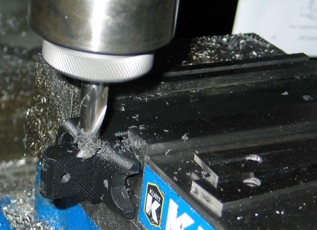
I opted to use up the rest of my MG47 filament for the various Liberator parts.  Unfortunately, I lost extrusion halfway through printing the receiver:

Rather than re-print the entire thing (which was over 30 hours), I decided to place the part in the mill vise and plane off the top, then glue on a replacement top half.

I took the opportunity to also glue in a metal block for compliance with the Undetectable Firearms Act.  I bought some 1″ square steel bar and sawed a piece off the end, then found a little bit of scrap to fill in the sides.  All told, I had 147 grams of steel, which should be more than sufficient to satisfy 922(p) (the specific section of US law codifying the UFA).

Insight is a powerful piece of 3D printing software, and I was able to go back to my sliced version of the receiver and delete all the layers from the file that I had already successfully printed.  This allowed me to print just the upper half of the receiver, and I printed a barrel at the same time for good measure.

Note that the .STL file for the Liberator barrel that was originally released is a smoothbore with no rifling (just like the original WWII FP-45 Liberator).  This theoretically makes it an AOW (Any Other Weapon) under the 1934 National Firearms Act (NFA).  The definition of an AOW is rather convoluted (and somewhat contested, given U.S. v. Davis), but it is intended as a catch-all category for firearms not otherwise defined by other categories (hence, ‘Any Other’).  A pistol or revolver with a smooth bore is generally considered an AOW, and for an unlicensed individual to make one, they need to submit a Form 1 to the ATF along with fingerprint cards, a passport photo, $200, and a sign-off from their chief law enforcement officer.  In other words, if you want to try printing a Liberator and don’t want a lot of hassle, make sure the barrel has rifling in it to avoid trouble.  Even modern reproductions of the FP-45 Liberator have tiny (and ineffective) rifling grooves in order to remain compliant.

I made sure to add rifling to the print itself, as rifling it afterwards would necessitate equipment that I simply don’t have (but would love to build someday).

Although the top half of the receiver printed without loss of extrusion, there was still a significant amount of warp on the bottom.  I opted to mix up a batch of epoxy with microballoons and colloidal silica (a thickener) to glue the two halves together.

I didn’t actually print the needed pins and just used some spare sections of metal tubing instead.

Meanwhile, Joe used his Lulzbot to create a remarkably robust receiver out of standard PA-747 filament.  He had tweaked his machine to provide extraordinarily dense prints with virtually no porosity.  We decided to test out his version to determine just how well the design works, its durability, and to get some velocity data to determine actual muzzle velocity.  Additionally, news stories on the Liberator seemed to generally claim that a $10,000 (or more) 3D printer was required to print the Liberator.  We wanted to dismiss this notion and show that even a $1000 printer is perfectly capable of printing high strength objects.

In mid-May of last year, we met up to actually perform the testing.  Our test rig consisted of an 80/20 frame to actually mount the Liberator to, which itself we clamped to a folding table.  In front of the test rig, we set up the sensors for my PACT chronograph (used to measure the speed of the fired bullet).  For safety, we used a 30 foot length of paracord to pull the trigger.  Note also that we used machine screws to actually mount the breech block within the receiver, rather than 3D printed pins.  Additionally, Joe’s barrel was slightly longer than the published Liberator barrel.

We had a great deal of difficulty getting the gun to fire in the first place, making nearly ten attempts to get it to go ‘bang’.  The first issue was getting the sear tail to actually release the hammer, so we replaced the trigger bar with one printed on my machine.  After this, the primer was indeed getting struck, but it did not seem to be igniting – we replaced the springs with ones from my machine as well.  We would wait 30 seconds after each attempt in case there was a hangfire (thankfully we never had one during the testing).  We wondered if headspacing could be an issue, so we pulled Joe’s barrel and put in one that I had printed on my machine.  We also replaced the .380 cartridge we had been using with a fresh one in case it was a dud.

Our next attempt did indeed go ‘bang’, and there was very little of the barrel left in the receiver.  My Stratasys FDM 1600 still has a bit of porosity in its output, and I hadn’t done a solvent vapor treatment on the barrel as was recommended by Defense Distributed.  Also, the round was a very tight fit and had to be pressed into the barrel – it’s possible that the bullet became dislodged, seating further down within the case and causing higher pressures when fired.  While the barrel was destroyed, we finally achieved primer ignition, so we put Joe’s barrel back in and continued testing.

With things finally working (if not smoothly), we proceeded to fire off as many shots as we could manage during the available sunlight.  Here’s a short video of the successful shots made: Lulz Liberator testing video

The video hints at some of the issues we ran into during testing.  We didn’t have the retainer for the firing pin installed, so the firing pin would rocket out the back during every shot.  We used a piece of masking tape on one attempt (you can see it fly up after the shot) to try and keep the firing pin in place, but the hole punched through the tape shows that this did not work at all.  We only had one roofing nail, but fortunately Joe happened to have along extra machine screws that he used for assembly and was able to fashion a replacement firing pin each time by cutting and filing it with a pocket multitool.  We had to make the firing pin longer each time as well, since each subsequent shot increased the headspace, with the cartridge becoming seated further and further down the barrel each time.

The 3 screws holding the breech block in place also became noticeably bent as testing continued, so we replaced them halfway through.

Here’s what the Lulzbot printed barrel looked like after its first successful firing.  The cartridge has actually been pushed back a bit (hence pushing back on the breech block and bending the retaining screws as noted).  You can also see white spots forming (known as crazing) as a result of the internal stress.  Finally, the primer has been pierced, allowing gas to erupt out the back of the cartridge, which is an undesirable behavior.  However, this is not a fault of the Liberator’s design, but a side effect of using a roofing nail or ‘field expedient’ machine screw – the sharp nose of the nail or screw actually punctures the primer cup, whereas proper firearm firing pins actually have a carefully rounded nose so that they dent but do not pierce the primer.  In fairness, however, pierced primers are not a great concern on a disposable firearm such as the Liberator or its WWII ancestor.  Continually piercing primers will allow the hot gases to erode the bolt face, firing pin hole, firing pin tip, etc. in a conventional firearm, but for a disposable gun designed to operate only a few times, this is admittedly a minor design quibble.

One thing the photo does not really indicate is how firmly the brass case is actually stuck inside the barrel.  In a conventional metal barrel, the brass does expand somewhat during firing, which is actually beneficial in sealing the case to the chamber walls in a process known as obturation.  The brass relaxes slightly as the bullet exits the barrel (which allows the internal pressure to drop back down to atmospheric levels), but since ABS plastic is much lower in strength than steel, the brass case expands greatly in the Liberator making conventional extraction all but impossible.  In our case, we needed to use a hex wrench and a rock to beat the expended cartridge out of the barrel.

Unsurprisingly, the walls had expanded so far that the case had actually split.

More surprising to us, though, was the fact that the barrel bore looked entirely unscathed (not only by the projectile, but by the hot propellant gases).  The photo really doesn’t show it, but in looking down the bore, the finish appeared just the same as in the unfired state.  Both Joe and I presume that there is so much bore expansion during firing that the bullet itself isn’t even touching the rifling.  Granted, the rifling would have done almost nothing anyhow (a copper jacket is still much harder than ABS plastic).

We only managed to record two shots with the chronograph (we weren’t using skyscreens, and they probably would have helped).  The captured velocities were 498.2 and 465.1 fps, for an average of 481.7 feet per second (146.6 m/s).  By comparison, the very same round fired out of a conventional .380 pistol will be well over 900 fps.  Consider that kinetic energy (or ‘muzzle energy’ in firearms parlance) increases as the square of velocity, and the difference is quite dramatic – the Liberator only achieves a muzzle energy of 49 foot-pounds, or roughly a quarter that of what a standard .380 pistol provides.  By way of comparison, a major league fastball delivers twice as much energy, and one person has actually died as a result of being struck with such a pitch (yet a year later, despite proclamations of mayhem and anarchy in the press, there have been zero deaths or even injuries from 3D printed guns).  In the end, then, the Liberator is not at all a weapon of physicality, but a weapon of philosophy, able to challenge preconceived notions regarding governmental control over the sharing of information.  Which, whether you agree or disagree with his views and actions, is precisely what Cody Wilson set out to accomplish in the first place.

Somewhat unsurprisingly, only a few days after DD posted the .STL files for the Liberator on their site, the US State Department sent a letter to Cody, demanding takedown of the Liberator files and 9 other designs that had been posted on Defense Distributed.  The authority for this stems from ITAR, the International Traffic in Arms Regulations, which controls import and export of defense related articles, including information related to such items.  That acronym may ring familiar to old hands of the internet, as it is the very same statute under which the US government blocked export of Phil Zimmermann’s PGP encryption software in the mid-90s, which saw Phil under criminal investigation for “munitions export without a license”.  While the case against Phil was eventually dropped (and Cody/DD have not been actually charged with any wrongdoing), the parallels are striking.  Like Phil’s case, it will undoubtedly be many years before the issue is resolved.

What struck me oddly about the State Dept. letter were the 9 other designs listed as takedown targets.  In my opinion, these were picked entirely at random in a perfectly transparent attempt to hide the fact that the Liberator files were in fact the sole items of interest.  Specifically, item 6, “Sound Moderator – slip on” was actually designed by noted RepRap contributor (and airgun enthusiast) Vik Olliver and is still available on Thingiverse.  If this was truly an ITAR violation, then why did the State Department not do anything when Vik originally ‘exported’ the file from New Zealand to Thingiverse servers in the US, and why has Thingiverse/Makerbot/Stratasys not received their own ITAR takedown letter for continuing to host this design?  I could opine a great deal more on the topic, but since I attempt to limit my blog writing to technical matters, I’ll curtail my musings.

Other interested people have printed their own versions of the Liberator as well – mashable.com has a superb 8 minute documentary called “I Printed a 3D Gun“, which I highly recommend watching.  Travis Lerol (who has also experimented with printing AR lowers on his 3DS Cube) attempts to give his own Liberator a try, but it fails to ignite (spoiler alert).  Travis tells me that he has since managed to get a round to fire, though it took about 200 attempts.  A number of design remixes of the Liberator concept have also been posted online, though very few (if any) have actually been printed and tested.

I was very honored to be asked by Professor Hod Lipson to make a presentation at the Chicago Inside 3D Printing conference on the topic of 3D printed firearms on July 11.  I was scared stiff to do any sort of public speaking, but thankfully there weren’t many people in the audience, and I had a few friends in attendance for moral support.  I’m very glad I attended, as I was able to chat with so many notable people in the field – not only Hod Lipson, but Avi Reichental (of 3D Systems), Scott Crump (of Stratasys), Scott McGowan (of Solid Concepts) and especially Ralph Resnick (of NAMII) – thanks to you all for your time and attention.  Chatting with Scott McGowan and some of the other folks from Solid Concepts was especially interesting, given that only a few months later, Solid Concepts would release their own 3D printed gun, the 1911 DMLS.  As a fan of John Browning‘s entire portfolio of work (and especially the M1911 pistol), I was thrilled to see such an iconic, century-old design recreated with cutting-edge technology.  Solid Concepts is now actually selling the 1911 DMLS in a limited run of 100.  While I wish I could afford one as a collectible (Scott, if you have an extra, please drop me a line!), I’m simply happy to see the whole 3D printed gun media story finally reach its logical conclusion: 3D printing is simply another manufacturing technology, and its application to firearms is no different than the development of milling machines, investment casting, CNC, polymers, and on and on.

Addendum: I had initially wanted to cover much more of the work done in the past year by others exploring the intersection of gunsmithing and 3D printing, but this post took long enough to write as it was.  Fortunately, Andy Greenberg (who interviewed Joe and me for several stories last year, and is a superb technology reporter) has an excellent rundown of the various designs being experimented with by FOSSCAD.

Gunsmithing with a 3D printer – Part 4

Well, to say that a lot has happened since Part 3 would be something of an understatement.  To recap: Defense Distributed tried printing my AR lower STL on an Objet machine, but it only held up for 6 shots.  While much was made in the media about this ‘failure’, I thought it was actually an […]

Well, to say that a lot has happened since Part 3 would be something of an understatement.  To recap:

Defense Distributed tried printing my AR lower STL on an Objet machine, but it only held up for 6 shots.  While much was made in the media about this ‘failure’, I thought it was actually an excellent demonstration of material properties in the two different 3D printing technologies used.  My FDM printed lower used material with a higher impact strength, while the Objet printed lower was stiffer.  As a result, mine flexed and would not cycle properly with .223 ammunition, while Defense Distributed’s lower cycled perfectly with 5.7x28mm ammunition, but fractured at the root of a buffer tube thread (interesting how the extreme detail afforded by the Objet process actually created stress risers due to the threads in my STL model being perfect ‘V’ profiles with no filleting of the thread roots).  They’ve since refined the model to hold up for 600+ rounds, which is quite impressive for a photopolymer.

Representative Steve Israel started calling for renewal of the Undetectable Firearms Act, and has also called for making 3D printed firearms and homebuilt ‘undetectable’ polymer magazines illegal.  I’m taking this somewhat personally, as he keeps using a giant photo of my AR lower as .22 pistol during his press conferences – the least he could do is put my URL on the photo to provide proper attribution.  Given that some of the most popular rifle magazines commercially made today are of polymer construction, I’m not sure what he’s really hoping to accomplish by expanding a law that was passed due to media hysteria over the introduction of the ‘plastic’ Glock pistol.  Wait, media hysteria over plastic guns?  The more things change, the more they stay the same…

After the horrific shooting in Connecticut, Thingiverse pulled almost all of the firearm related files, including my AR lower and a Magpul style trigger guard I had designed.  I immediately contacted their legal counsel and pointed out that a trigger guard is a rather important safety device and has use in paintball and airsoft, not just firearms.  The response was ‘our sandbox, our rules, and we can change the rules at any time’ (but spoken in far more lawyerly terms).  An AR-15 grip that had also been taken down was reinstated a few days later, so I’ve been asking how to get my trigger guard reinstated as well.  However, my requests appear to be ignored, and I’m somewhat giving up on Thingiverse at this point.  It’s still a great community, but when I can’t use it to share with other gunsmithing hobbyists or even paintball and airsoft enthusiasts, my desire to use it naturally diminishes.  Meanwhile, Thingiverse appears to have no issues with people sharing drug paraphernalia designs, so maybe they’re attempting to cater to a rather different group of ‘hobbyists’.

For anyone interested, I have a copy of my original AR lower STL here (though I don’t really recommend it at this point – there are much better 3D printable lowers that have been designed and refined by other folks).  I have a copy of the trigger guard here.  It comes in two versions – one is the standard version that uses a roll pin through the rear holes, and the other I designed to be a tool-free version that uses angled studs to snap into place.  I’m actually rather proud of this version, and would be happy to hear feedback on it.

Back to the present – I really haven’t done anything further with the printed AR lower, as I’ve been experimenting with a different firearm platform.  Commenter Allen had asked “Could the Ruger 10/22 receiver be built the same way?”  This certainly got me wondering, as the 10/22 receiver, unlike an AR-15 lower receiver, is what the barrel attaches to, and contains the reciprocating bolt.  Additionally, the fire control group (trigger, hammer, etc.) is contained in a modular pack rather than having those components fitted individually to the receiver.  Plus, answering this question seemed like an excellent excuse to finally purchase a 10/22 – like the AR-15, it’s an incredibly popular rifle with countless aftermarket accessories available.  Additionally, it’s a great platform to learn the fundamentals of proper marksmanship (one of the many skills that I’d like to learn one of these days).

I found a very well used one at Gander Mountain for a reasonable price – the sling swivels had apparently broken off long ago and the receiver finish was a bit worn, but it looked to be in good functional order and would do well for learning how the rifle operates and is constructed.  When I got it home, I eagerly dug into the disassembly to see how it functioned and to give it a much needed cleaning.  The 10/22 is a semiautomatic, blowback operated .22 rifle.  The blowback operation means that unlike the AR-15, the bolt is not locked into place when the gun is fired and is only kept forward by means of the recoil spring.  A blowback bolt is also quite heavy in comparison to the cartridge used – this is to ensure that the bolt begins its rearward travel in the firing cycle slowly enough to let the chamber pressure decrease to a safe level before the spent cartridge is extracted.  The receiver itself is cast, though there are aftermarket billet receivers available for those looking to heavily customize the rifle.  In looking at how the bolt reciprocates in the receiver, it appeared that there should be no issues with a 3D printed receiver, provided that the print is made so that the layers are parallel to the barrel axis (to provide as smooth a surface as possible for the bolt’s travel).

For the printed receiver itself, I again turned to Justin Halford’s cncguns.com for an IGES file.  Unlike the AR-15 lower receiver, there weren’t any design features that I felt needed strengthening right away, so I created an STL file directly from the solid model and set it running with the same Bolson black ABS I had used for the AR lower.  I printed the receiver upside down so that the interior didn’t need any support material, and thus would provide as good a finish as possible.

After removing all evidence of support material, it was time to start fitting parts.  Chief among these is the barrel itself, but the hole in the receiver was slightly undersized (not unexpected, and better than being oversized).  I clamped it to the angle plate on the mill and indicated it in vertically with a dial indicator and coaxially with a Blake co-ax indicator before opening up the hole with the boring head.

After bringing the hole to appropriate size (I could just begin to insert the barrel shank), I tapped the barrel clamp holes with 12-24 threads (thanks to the blueprints at fireamfiles.com) as well as the stock mounting screw hole in the front tang.

Next was to actually test installation of the barrel itself, which tightened up nicely, but I noticed that the barrel would visibly cant downward as I tightened the clamp screws.

After removing the barrel, I saw that there wasn’t quite enough clearance on the front counterbore, and the back of the barrel was catching on the top front edge of the receiver.  So it was back to the boring head to enlarge the diameter on the mating face slightly.

Then, it was time for a test fit of the bolt – it was a tight squeeze to get it past the rail on the inside right of the receiver.

As it turned out, I think the rear wall of the receiver in the original IGES file may be a touch too thick, as I also couldn’t get the trigger pack installed, so I thinned out the rear by perhaps 0.030″ until I could just get the retainer pins to go through the receiver and trigger pack (I had already reamed out the holes in the receiver at this point).

With that done, I could finally fit all the internals and actually dry fire the gun.

However, when I tried to drop the receiver assembly into the wood stock, it wouldn’t fully seat.  After fumbling with it for a few minutes, I noticed that there is an extra relief cut on the original receiver at the interface between the tang and the receiver front.  As it turned out, the original IGES file does indeed have this relief cut, but when I brought it into SolidWorks, I had run a feature recognition pass on the part.  For some reason, SolidWorks removed this feature – I should have just done a direct export to an STL file instead!  Oh well, one last machining pass on the mill took care of it.

The barreled action fit just fine in the stock, and both the 10 and 25 round Ruger magazines fit, though perhaps a little more loosely than desired.

Today I took it to the range and found an accomplice to act as a model.  Naturally, I let him burn through some rounds on the 3D printed AR receiver configured as .22 pistol first.  A .22 AR pistol is kind of a ridiculous contraption, but it is also ridiculously fun.

Next was the test of the printed 10/22 receiver.  As with previous testing, I started with only 1 round in the magazine and worked my way up.  Things were running just fine, so I put in the 25 round magazine and let ‘Secret Agent Man’ have some trigger time with it.

Generally, it ran nicely, though we did have some feed issues with it.  I think the fitment of the magazine could be to blame, as it seems that the front of the magazine is able to tip down a little too far.  Both magazines are also absolutely brand new (this was their first usage), and I’ve been told that 10/22 magazines operate better after an initial break-in period.

So there you have it – a 3D printed 10/22 receiver is entirely feasible!

Gunsmithing without a 3D printer 1

Last fall, my friend Max helped his mom pick out a shotgun for home defense.  Being a fairly small lady, she took a liking to a youth model 20ga. Mossberg 500 and had a great time with it at the range.  However, the 22″ barrel that came with it was a little long for a […]

Last fall, my friend Max helped his mom pick out a shotgun for home defense.  Being a fairly small lady, she took a liking to a youth model 20ga. Mossberg 500 and had a great time with it at the range.  However, the 22″ barrel that came with it was a little long for a home defense gun, and I was asked if I might be able to chop it down to the legal limit of 18″ (in the US, a shotgun with a barrel of less than 18″ is considered a short barrel shotgun, and is subject to NFA restrictions).  The small amount of gunsmithing that I’ve done has always been for myself, but I was happy to take a stab at the project (worst case, I’d just have to buy a new barrel to replace the screwed up one).  Additionally, I needed to attach a rail-mounted Streamlight flashlight to the shotgun (that has no rails).  Sounded like a fun challenge, so I ordered some odds-and-ends from Brownell’s in preparation for the task.

The first step would be to start hacking away on the barrel.  Since the barrel has a vented sight rib, you can’t just use a pipe cutter to cut the end off (besides, I never liked the thought of that method anyhow – it would leave a nasty burr on the inside, and is rather a crude approach when you have access to machine tools).  Also, 18″ is right through the front edge of a rib, and erring on the side of caution is highly recommended – I would have to trim the rail back to the rib and leave a bit of barrel sticking out underneath that to make sure I’m on the legal side of 18 inches.

I clamped the barrel in a padded vise and proceeded to use a number of wraps of electrical tape through the cut area – protecting the existing finish is paramount.  I’m a garage gunsmith, but I don’t want my work to look like it was done by a garage gunsmith – I’d like the result to be something I can personally be proud of, so I took extra caution to prevent errant nicks and dings.  I should also apologize for the horrendous pictures here – I left the protective plastic sheet in place on my phone, hoping it would help protect the lens (which it does, but when the LED ‘flash’ turns on, it illuminates the sheet and ruins the photo).

Measure twice, cut once.  Or in this case, measure at least half a dozen times – anything under 18″ isn’t an ‘oops’, it’s a federal crime (if you don’t have an approved Form 1 for the shotgun).

I cut through the rib with a cutoff disc in a Dremel and stopped before I hit the barrel.

Then I lopped off the end of the barrel with a hacksaw.

Next was to clean up the front of the sight rail and end rib.  I taped the heck out of the barrel stub end and then used a flat file to smooth out the end of the rail and give the corners just a little radius so they wouldn’t catch on anything.

I used some vinyl drawer liner material with double-sided tape to line the lathe chuck jaws.

With the barrel inside a plastic bag to help keep it protected, I took light facing cuts across the muzzle until all evidence of hacksaw-ery was eliminated.  Then I used a small piece of sandpaper to knock down the sharp inside and outside edges.

Since the barrel shortening had removed the front bead sight, I needed to drill and tap further back on the sight rail to remount the bead.  I clamped the barrel in the mill vise and eyeballed it to make the sight rail level.  I then used an edge finder to indicate in the sight rail so I could be sure of drilling right on its center.

I drilled just behind the front rib and carefully tapped it out with a 5-40 tap.  That was all for machining on the barrel itself – the bare steel simply needed bluing.  Unfortunately, I don’t have any photos of this, as I was trying to simply do the job correctly rather than documenting it.  However, my general approach was to first thoroughly degrease the surfaces to be blued (the end of the barrel and the front of the sight rail and rib).  I wiped them down with rubbing alcohol and started a pot of water boiling on the stove.  I would dip the end of the barrel into the boiling water for a little while to heat it up, then pull out the barrel, shake off any water droplets, and quickly apply Brownell’s Oxpho-Blue Creme to the bare steel areas with a cotton swab.  After letting the solution blue the metal for 30 seconds or so, I wiped it off and dunked the barrel end back in the boiling water to clean off the solution and re-heat the metal.  I repeated this perhaps 8-10 times.  When everything was done, I washed off the barrel end once more, wiped it off, and applied some Remington gun oil to the newly-blued areas to keep them protected.  I think the end result was perhaps a touch lighter than the factory finish, but it’s hard to tell, and might just be due to the machined/filed surfaces rather than being factory polished.  At any rate, it looked good.

Now, how to mount that pesky flashlight?  Originally Max and I were thinking of drilling and tapping the magazine tube (the tube under the barrel where the shotshells reside) for Picatinny rails.  While this might work, I’d have to figure out how to align the magazine tube properly in the mill vise, and I’d have to contend with what would likely be a thin wall on the magazine tube (and interfering with the feeding action would be a very bad idea).  I then figured that attaching a rail via scope rings would be the best method – not only would I not have to drill through the magazine tube, but the user could adjust the flashlight position though a full 180 degree arc.  I purchased a sight rail with scope rings, as I had a crazy idea – mount the rings to the magazine tube and flip the rail inside-out…  The rail needed a bit of machining – I had to add extra slots (for the cross-pin on the flashlight to lock into), and I needed to machine the rail’s underside on each end so that the scope rings could clamp onto it from underneath.  With all of that complete (forgot to take photos, sorry), I had to adapt the 1″ scope rings to the 7/8″ magazine tube.

I used some scrap 1″ OD tubing that had a 3/4″ ID, and bored out the interior to 7/8″.  I then sliced off two rings with a parting tool.

I clamped each ring in the mill vise and lowered the quill so that the slitting saw sat on the top of the ring.  Then I raised the knee up by half the outside diameter of the ring plus half the thickness of the slitting saw’s kerf.  Slotting each ring allows them to collapse slightly and grip the magazine tube when each scope ring is tightened.

The mounting system worked perfectly, and the flashlight was easily attached.

The resulting platform turned out great, and she’s very happy with it – that’s all I could ask for!

Gunsmithing with a 3D printer – Part 3

To say that the buzz generated around this project is heavy on “media hype” would be an understatement.  I could write a great deal on this alone, but I’ll content myself to refer people to David Chernicoff’s excellent article explaining why this is not a big deal and the apocalypse is not nigh.  Being at […]

To say that the buzz generated around this project is heavy on “media hype” would be an understatement.  I could write a great deal on this alone, but I’ll content myself to refer people to David Chernicoff’s excellent article explaining why this is not a big deal and the apocalypse is not nigh.  Being at the center of a story really lets one see how the media sausage is made, and I’m amazed at how much misinformation gets copied and introduced as a story gets picked up by a string of outlets.  It’s like a giant journalistic game of “telephone”.  The past few weeks have also seen a far bit of buzz on the Defense Distributed project, which aims to design a 100% 3D printable firearm.  It’s certainly an interesting engineering challenge, and one which I’ve pondered myself over the past year and a half.  The problem is that even the strongest 3D printable thermoplastic currently available for the FDM process (Ultem 9085) doesn’t even have half the tensile strength needed to withstand the 24000 psi maximum allowed chamber pressure of the .22LR round as defined by SAAMI.  As such, yes, a 100% 3D printed gun made on a RepRap could certainly go ‘bang’, but even with a barrel of large enough diameter to keep it from exploding, there would be so much deformation in the bore that most of the available energy would be sapped by gas leakage around the projectile (to say nothing of the utter lack of accuracy).  In the end, you’d have a smoking, charred crater left for a barrel bore after the single shot.  Quite an expensive proposition, given that such a gun would almost undoubtedly be classified as an AOW, requiring sign-off by a chief law enforcement officer, background check, submission of fingerprint cards, $200 for the tax stamp, and up to a 6 month wait for approval before you could commence printing one.  If you have an interest in hobbyist gunsmithing, make sure to familiarize yourself with the rules and regulations that your project would have to abide by – it’s not worth risking a paid vacation to ‘Club Fed’ to 3D print a ‘zip gun’ that could very well cause a great deal of injury to yourself and others.  Please stay safe and legal, everyone.

On a more interesting historical note, I found that my printed lower is not in fact the first 3D printed firearm to be tested (as per the GCA definition, where the receiver itself is legally a firearm).  Many people pointed me to the Magpul Masada, as the prototypes had SLS printed lowers and furniture.  However, the lower of the Masada is not the controlled part – it is in fact the upper receiver, which was machined aluminum on the prototypes.  No, the first tested 3D printed firearm as best I can tell was actually a silencer!  Yes, as per the definitions of the 1968 GCA, a silencer is by itself considered a firearm.  Admittedly, this starts splitting hairs, and there may very well be other examples of prior art – Magpul’s FMG-9 prototype was primarily built with SLS printed parts, but used a modified Glock 17 as the core, and I’m unsure of whether the receiver was Glock or SLS.  In fact, it may very well be that exactly what constitutes the receiver on the FMG-9 has yet to be decided – there has only been a single prototype made, and until the ATF’s Firearms Technology Branch is asked to determine which is the controlled part, it could be entirely unknown.  As well, firearms companies have been incredibly secretive about their usage of rapid prototyping (I’m still trying to track down specifics on the SLA silencer) – I imagine there’s some engineer out there saying “Boring!  I did this stuff like 10 years ago!” but can’t say a word due to non-disclosure agreements.

Anyhow, back to tinkering.  While the tests on the printed lower ran just fine with .22 ammunition, the real test would of course be the round that the AR-15 was designed for, the .223 Remington cartridge.  I re-assembled my original DPMS 20″ bull barrel upper and attached a collapsible stock to my printed lower.

Again, with a fair bit of trepidation (though tempered with an engineering background), I used only a single round to begin with, which functioned just fine.  A much louder report than .22LR to be sure, but I was pleasantly surprised by the utter lack of recoil – Eugene Stoner was a very sharp fellow, and despite my misgivings about a direct impingement system versus a piston based system, I’m impressed by how effectively his design works.  However, when adding more rounds to the magazine in testing, I had issues with extraction and feeding.

I switched out my printed lower for my aluminum lower and tried again.  To my chagrin, the problems persisted, so I stopped testing, wondering if perhaps the steel-cased ammo I was using could be to blame.  The fact that I still didn’t have a detent for the rear takedown pin was also bothering me, as it meant that I didn’t yet have a fully functioning 3D printed lower (and as things loosen up and wear in, the rear takedown pin tends to drop out onto the floor without the detent in place).  I purchased some 1/8″ OD brass tubing with an ID suitable for the detent spring from McMaster-Carr and set about machining an insert that would house the spring and detent.

I did have to drill out the front of the tube slightly, as the detent is a little larger in diameter than the spring itself.  I also tapped the rear of the tube for 4-40 threads so that a set screw would keep the spring in place without any need for an end plate (so the lower can be operated as a .22 pistol with absolutely nothing screwed into the buffer tower).

After drilling out the hole in the lower to 1/8″, I pressed in my machined detent tube (with set screw, spring and detent) with a dab of solvent to secure it in order to capture the tube in the lower receiver.  It would have been nice if Stoner would have made the lower receiver so that it didn’t require such work, but realistically, an AR-15 stock would rarely (if ever) need removal (in fact, proper assembly procedure is to stake the rear plate in place after the castle nut is tightened).

I then gave the upper a good cleaning and oiling – while it was still brand new, the fact that I had purchased it a good 6 years ago meant that it was extremely dry.  I also purchased some brass .223 ammunition, as some uppers just don’t like steel cased ammo, and I wanted to improve my chances as much as possible.  Testing with the brass cartridges and freshly cleaned upper yielded excellent results with the aluminum lower, with perfect cycling.  Swapping in my printed lower, however, brought the old feed and extraction issues right back.  So, what could be the issue?  My primary suspect is flex in the buffer tower.

There is a small gap between the upper and lower, and this gap does indeed widen as the rifle is cocked due to the increasing force from the action spring located in the buffer tube.  Without a spring installed, the gap is about .027″, and with the spring installed, the gap is about .034″.  Pulling the charging handle all the way back widens the gap to .040″.  As such, the buffer tube actually gets flexed downward when the BCG (bolt/carrier group – the primary reciprocating components in the rifle) is moved to the rear during the firing cycle.  Since the BCG actually slides into the buffer tube, keeping the tube and the upper receiver axes aligned is critical, and binding results from this flex, causing the feed and extraction issues.  I decided to do a bit of rough FEA (Finite Element Analysis – computer simulation of the actual bending) in SolidWorks to see how well it matched what I was actually seeing on the printed part.

I used the default parameters for ABS and applied a rearward force of 15 pounds (the approximate force I measured with a fish scale needed to begin moving the BCG rearward) to see what the calculated deformation would be.  As it turned out, the model says that the buffer tower should actually be bending about 0.011″ rather than the .007″ I was seeing, and that was with the stock ABS values, not values that would better represent the weaker 3D printed part (as opposed to something injection molded from the same material).  I think the buffer tube and end plate themselves provide the extra rigidity that real-world measurements are showing, and I’ll have to see how I can best simulate their addition.

Meanwhile, I know that the buffer tower is not as large as it should be – the new ATI Omni lower is bulked up even more than my version on both the buffer tower and front takedown lugs.  As a side note, my front takedown lugs have cracked once more where the layers had originally split, so my current design is not sufficiently robust in that area either.  Bulking up my lower’s buffer tower to a similar state as the ATI lower shows that the tower would bend only about .008″ in the simulation.  However, even that may not be sufficiently rigid.  Commercial polymer lowers are not made of ABS, but are instead a glass filled Nylon 66, which is far stronger.  Even using unfilled Nylon 6/10 in the simulation brought the flex down to only about a quarter of that of ABS – still close to an order of magnitude more bendy than aluminum, but probably in the range of reliable functionality.

As such, I think the best way to use a 3D printed AR-15 lower with .223 is to better support the buffer tube from underneath.  Oryhara has done precisely that with his thumbhole buttstock design.  While he’s only fired it so far with a .22 upper, I’m guessing he’ll have much better operation with .223 than I have.  In the meantime, I’ll try applying a bit of carbon fiber to the buffer tower (and front lugs) on my printed lower and see if the feed and extraction demons can be tamed somewhat.

Gunsmithing with a 3D printer – Part 2

I know I’m not alone in having printed an AR-15 lower and test fitting it with internals – this fellow printed an upper to go with his printed lower, and another Thingiverse user just printed an AR-10 lower! I’d be pretty hesitant to use a printed lower with something as powerful as .308 (hence why […]

I know I’m not alone in having printed an AR-15 lower and test fitting it with internals – this fellow printed an upper to go with his printed lower, and another Thingiverse user just printed an AR-10 lower! I’d be pretty hesitant to use a printed lower with something as powerful as .308 (hence why I’m starting with .22), but I am impressed that a bulked up AR-10 lower can still be printed on something the size of a Prusa Mendel.  I’m sure many others have also printed AR-15 lowers, but I can’t find any indication of anyone having actually fired one.  I’m sure my printed lower will hold up just fine, though the response of many firearms owners is essentially “You’ll shoot your eye out, kid.

Before I can put my money where my mouth is, however, I need to actually have a complete upper receiver.  This weekend I finally got around to attaching the CMMG pistol length barrel that I have to an upper that I purchased many years ago.  I’m not sure why CMMG decided to stake the front sight/gas block in place when it needs to be removed anyhow to attach a barrel nut, but I managed to drive the retaining pins out of the gas block, remove it, slip a barrel nut in place and re-attach the gas block.  Why am I going through this trouble?  Because due to the quirks of US law, a receiver can be switched back and forth between rifle and pistol configurations only if the first incarnation of the receiver assembled into a complete gun was as a pistol.  I don’t want to limit myself, so the printed lower will begin life as a pistol in order to comply.

This subject of the upper receiver brings up another point – people have asked me if the upper could be printed as well, and I’m not nearly as confident of such a part as I am of a printed lower.  When installing the barrel to the upper receiver, I found that the minimum barrel nut torque is defined as 30 ft-lbs (with a maximum of 80 ft-lbs allowed when ‘timing’ the barrel nut so that the gas tube will align in one of the notches on the barrel nut).  I really doubt that an unreinforced thermoplastic can take up to 80 ft-lbs of torque on 1.25″-18 threads, especially given all the discontinuities present in a printed part.  It’s probably sufficient to use less torque, as the barrel nut simply keeps the barrel attached to the upper receiver (and I believe the Bushmaster Carbon-15 uppers, which are a carbon reinforced polymer, specify a lower torque).  All of the force from the shot fired is held between the bolt lugs and matching faces on the barrel extension, not between the barrel nut and upper receiver.

Assuming you had printed an upper receiver and didn’t overtorque the barrel nut, it would probably work fine.  For a little while, at least.  The problem with the AR-15 and its derivatives is that the gun ‘craps where it eats’.  Many modern rifles are gas operated, meaning that they divert some of the hot expanding gases from the barrel to actually recock the gun (as opposed to being recoil or blowback operated).  The AK-47 and AR-15 are both gas operated, but the Kalashnikov has the hot gases acting on a piston very near to where the gas has exited a tiny cross-drilled hole in the barrel.  The piston is connected to the bolt carrier, and every time the gun is fired, gas pressure on the piston pushes the bolt carrier back, cycling the gun.  In the AR-15, the gas is directed through a long tube all the way from the hole in the barrel right up to a ‘gas key’ attached to the top of the bolt carrier.  This allows for much less reciprocating mass (which means that the AR-15 has much lower felt recoil than its Russian counterpart), but with the disadvantage that all of those hot gases (and other crud that comes from burning gunpowder) are blown right into the chamber above fresh rounds in the magazine – hence, ‘craps where it eats’.  Since FDM style 3D printers use thermoplastics as a feedstock, these hot gases will undoubtedly start melting a printed upper.  In fact, I’ve heard reports of reinforced polymer uppers starting to melt after repeated rapid fire.  Fortunately, piston systems are becoming more widespread on the AR-15 platform, which would eliminate the ‘hot gas melting the upper’ issue, but I’d still be hesitant to try using a 3D printed upper even for just rimfire cartridges – reinforcement would be needed, I think.

Since I’m using a CMMG .22 kit, it doesn’t need a buffer and buffer spring (which is great, as I don’t have those parts anyhow).  In fact, it doesn’t need anything attached to the rear of the lower receiver at all, but I wanted to have something in place to help provide support for the ‘buffer tower’ (the ‘loop’ at the top rear of the lower receiver). More importantly, I wanted an excuse to finally use the nice 1-2″ thread pitch micrometer that I bought several years ago.

I stuck a piece of 1.25″ scrap aluminum rod in the lathe, and turned some threads onto it.

When the micrometer indicated I was getting close, I threaded on an actual aluminum lower to test for fit.  Afterwards, I opted to fit out the lower with internals as well, as I figured it was prudent to test the untested upper and .22 conversion with a ‘proper’ aluminum lower first.

This morning I hunted around for ammunition, which took me a good 20 minutes (while I am a firearms enthusiast, I don’t think I’ve fired more than a dozen rounds or so in the past 5 years).  After realizing that I had no .22 ammo (yet discovered cartridges for guns that I do not own), I made a stop at the manliest store on the planet to pick some up (if Bruce Campbell were a store, he’d be Fleet Farm).  I then headed to a top secret testing facility (Dad’s farmland) and carefully assembled the upper onto the aluminum lower.  Absolutely nothing had been previously tested, and this was actually the very first AR-15 I’ve assembled (or even owned), so it was with a fair bit of trepidation that I loaded a magazine into the gun (with only a single round – always test unproven systems with a single round to begin with).  After cocking it and carefully letting the bolt forward to chamber the round, everything looked to be in place, so I aimed (as well as one can ‘aim’ with nothing attached to a flattop upper) 20 feet away into the dirt and fired.  Everything worked fine, so I reloaded with 2 rounds and repeated, followed by 3 rounds.  All systems functional!

I switched out the lower for my printed version and double checked the operation.  Would it hold up?  Again, one round in the magazine, cock the gun, squeeze the trigger, and…  Wouldn’t you know it, I shot my eye out.  Just kidding – it functioned perfectly.  Testing again with 2 rounds, then 3 rounds, then a full magazine.  Everything ran just as it should, magazine after magazine.  To be honest, it was acting more reliably than a number of other .22 pistols I’ve shot.  I ran close to 100 rounds through the gun before getting annoyed with not actually being able to aim at anything, and decided to call the experiment an overwhelming success.

To the best of my knowledge, this is the first 3D printed firearm (as per the definition in the GCA) in the world to actually be tested.  However, I have a very hard time believing that it actually is.  My Stratasys is a good 15 years old, and Duke Snider’s original AR-15 CAD files have been floating around on the ‘net since early 2000.  As such, I can’t imagine that I’m the first person stupid adventurous enough to actually pull the trigger on a 3D printed receiver.  If someone has beaten me to it, please leave a comment!

Gunsmithing with a 3D printer – Part 1

I’ve used my Stratasys to prototype out various ideas for paintball gun parts, but the concept of using it for actual firearm parts hadn’t really occurred to me until early last year.  I first thought of making some dummy 12 gauge shells to test out the action on a Remington 870, and then thought of […]

I’ve used my Stratasys to prototype out various ideas for paintball gun parts, but the concept of using it for actual firearm parts hadn’t really occurred to me until early last year.  I first thought of making some dummy 12 gauge shells to test out the action on a Remington 870, and then thought of using it to test out 1911 pistol grip panel ideas.  Gun manufacturers have been using rapid prototyping for years, and the concept is now making its way to the hobbyist gunsmith.  To the best of my knowledge, this has been restricted to mockups (Justin Halford used a stereolithography made frame to test component fit for his fantastic Beretta 92FS project) or less critical parts like furniture (grips, buttstocks and such). It wasn’t until I came across an AR-15 magazine follower on Thingiverse that I began to wonder about the feasibility of making more functional parts with a rapid prototyper.

The use of plastics in firearms is a relatively recent development as far as primary structural components go.  Firearms have certainly used plastics early on (the use of phenolic ‘Bakelite’ was popular for grips and other previously wood furniture in the years leading up to WWII and well afterwards), but use of plastics for a core component took much longer.  Consider a car analogy – we’ve seen plastic dashboards for many decades, but the use of plastic for something as critical as an engine block wasn’t attempted until the early 1980s.  It wasn’t until 1959 that Remington (at the time owned by DuPont, hence having access to cutting edge polymer technology) came out with a .22 rifle that used plastic for the receiver (the core ‘body’ of the gun).  This was the Nylon 66, so-called since the Zytel-101 material used was a type of Nylon 6-6 polymer.  While it was quite a popular rifle (selling over a million units by the time it was discontinued in 1991), and helped further the use of synthetic stocks among shooters, it wasn’t until Glock pistols became popular that polymer firearm frames/receivers gained widespread acceptance.  Today, polymer framed pistols outsell their metallic counterparts, and new rifle designs increasingly use molded synthetic receivers.

The AR-15 rifle, while designed to use an aluminum lower receiver, has such limited force imparted while firing that I guessed it could probably be made of printed plastic with little worry of breakage.  After all, Orion’s Hammer has successfully made a lower from HDPE (after having limited success making one from a pine board), not to mention the commercially produced polymer receivers such as Bushmaster’s Carbon 15 and Plum Crazy C-15. It would easily fit within the build volume of the Stratasys, but my concern was whether or not it would have enough precision for all features to be usable (Orion’s Hammer didn’t worry about the takedown pin detents or bolt catch, for example).  Rather than waste a lot of material on a failed idea, I took Justin Halford’s IGES file of the lower, scaled it to 75% of full size, and set it running with PP3DP filament.  The resulting print looked fantastic:

Figuring that my chances with a full scale print were excellent, I decided to modify the model by strengthening two areas that I was slightly concerned about – the front takedown pin lugs and the bolt hold catch lugs.  Adding more material to the model in SolidWorks was pretty straightforward, and I finished it up by adding an integral trigger guard.  I switched out the PP3DP filament for some black Bolson ABS – after all, the ‘black rifle’ would look a bit odd in ivory (more importantly, it’s easier to see/photograph detail on dark material).  After slicing the STL file, I sent it to the Stratasys and waited a few days (no speed demons, these old machines).

After breaking away all of the most easily removed support material, I had a great looking print.  I had generated the STL file at a very high resolution, as I was wondering how well the buffer tube screw threads would actually turn out (having not yet tried printing any threaded objects).  As it happened, perfect!  A buffer tube screwed right into the threads with no cleanup required.  Naturally, I wanted to share my results, but unfortunately firearms are presently a bit of a touchy subject.

The concept of using a 3D printer to manufacture gun parts has not been lost on the RepRap community, and the topic has been debated a number of times on the RepRap forums.  At this point, there is a policy proposal to not allow weapon designs or projects to be uploaded to the RepRap library, and a line on the Health and Safety page for the RepRap project states “the RepRap researchers will work actively to inhibit and to subvert the use of RepRap for weapons production” (emphasis mine).  On the other hand, Thingiverse once had a rule against weapons in their terms of service, but later removed that restriction.  Afterwards, the Thingiverse upload page still said “Please don’t upload weapons. The world has plenty of weapons already,” but I assumed that this text was not updated after the TOS was revised.

I decided to ask for clarification on the Thingiverse mailing list.  The phrase “kicking the hornets’ nest” aptly describes the resulting discussion, I think.  In the end, Zach ‘Hoeken’ Smith (one of the Thingiverse founders) weighed in and clarified that such content is allowed, though discouraged. Fair enough. Apparently someone had taken notice of the commotion, and three weeks later, there was an STL file of a lower receiver posted to Thingiverse in what could be described as a confrontational manner.  Since the cat was out of the bag, I decided to upload my own STL model, as I wanted to hear constructive feedback on how the version might be improved to better suit the current limitations of 3D printing.  Well, apparently the resulting ‘weapons on Thingiverse’ debate raged hard enough that in February the lawyers were unleashed upon the site’s Terms of Use, and now uploading any content that “…contributes to the creation of weapons…” is verboten. Although that policy doesn’t appear to be enforced, I suppose they could yank my uploads and kill my account at any time, hence I’m re-documenting my work here.  Enough rabble-rousing – back to the fun stuff.

I’m rather jealous of people who can print the lower receiver with soluble support, as clearing support material from small diameter holes is a bit of a pain.  I used a pin vise and an assortment of small diameter drill bits to clear out all the long cross drilled holes in the part, using Duke Snider’s receiver blueprint for dimension references.  With all traces of gray polystyrene eradicated, I set about cleaning up the larger holes, as they were ever so slightly undersized (better than being oversized).  I ran a 5/32″ drill bit through the holes for the trigger and hammer pins, and eagerly installed the fire control group.  The trigger and hammer  functioned flawlessly, with no slop apparent in the pins.  The selector lever was a bit of a tight fit, so I worked it back and forth perhaps a hundred times to break it in.  After tapping the 1/4-28 thread for the grip screw, I attached the grip, keeping the selector in place by virtue of its detent.  Similarly, the magazine catch was a bit of a tight fit, and I had to carefully work the part back and forth in the receiver to make sure that it would reliably retract under force from the magazine release spring.  I then ran a 1/4″ drill bit through the holes for the front and rear takedown pins.  Unfortunately, I heard a quiet snap when drilling out the front hole, and sure enough, there was a break between layers.

On the plus side, this confirmed my suspicion that the takedown lugs needed reinforcement in the first place.  I brushed on a bit of Weld-On 3 to fuse the layers together (delicately, recalling what happened when I dunked printed parts in MEK).  After running a drill bit through once more, the cleanup was complete, and I installed the takedown pin with its spring and detent.

Nice!  Now, for the other area that had given me concern – the bolt hold lugs.  Sure enough, when I pressed in the roll pin, I had layer separation.

Well, I never cared much for roll pins anyhow – they always seemed rather brutal (especially when driven into a blind hole – yikes).  After touching up the damage with a few more dabs of Weld-On 3, I ran a 3/32″ drill bit through the hole.  I then threw away the roll pin and instead used a dowel pin of the same size.

A little bit of superglue on either end of the pin should suffice to keep it in place.  Finally, there was the rear takedown pin to contend with.  Justin’s model appears to have the recess for the pin head as around 5/16″ or so, while the head on the pin from my DPMS parts kit measures 3/8″.  No worries – I lightly clamped the receiver in the mill vise, centered the spindle over the hole, and carefully widened the counterbore out with a 3/8″ endmill.

After this, the takedown pin fit perfectly.  Since I don’t actually have a full AR-15 stock (and will be attempting to run this receiver as a pistol first), I needed a way to capture the detent spring for the rear takedown pin.  I opted to tap 4-40 threads in the rear of the spring hole and kept the detent and spring in place with a 1/8″ long 4-40 set screw.  Unfortunately, the force on the detent was heavy enough that when I tried to slide the takedown pin into the receiver, the detent broke through the thin wall into the rear of the FCG area.  It appears that extra 1/8″ of spring compression due to the set screw may be too much.

I dabbed on a bit of ye olde Weld-On 3 and clipped 1/8″ off of the spring to compensate before attempting to secure the pin again, but the detent still wanted to break through the wall.  I’ll leave it out for the time being, but I’m considering drilling the hole out larger and sleeving it with brass tubing.

Overall, it’s looking quite promising.  The upper receiver fits snugly, and magazines can be inserted and removed with ease – shown is the lower with an upper attached along with a .22 magazine that I intend to use with the CMMG .22 conversion kit.