Once I had the big Keiyo Seiki settled in place in the garage, attention turned to the question of “how the heck do I power this monstrosity”? For my Tree 2UVR vertical mill, I have a borrowed VFD (Variable Frequency Drive), which is able to transform the 240v single phase power (the same type of […]
Once I had the big Keiyo Seiki settled in place in the garage, attention turned to the question of “how the heck do I power this monstrosity”? For my Tree 2UVR vertical mill, I have a borrowed VFD (Variable Frequency Drive), which is able to transform the 240v single phase power (the same type of circuit a house would have for an oven, for example) into the 240v three phase power that the mill needs. It’s roughly analogous to the problem of powering a US intended appliance in the UK (120v versus 240v, respectively), only in this case additional power phases are needed. Three phase power is how electricity is actually generated and distributed as part of the electrical grid – when you look up at a large electrical tower, you’ll almost always see 3 wires (or a multiple of 3). These aren’t for the ground, neutral and ‘hot’ wires of a standard electrical outlet, but are rather the 3 phases of power generated by the utility. One of those phases gets split off and lowered in voltage through a variety of transformers to supply the 240v and 120v single phase power that your house uses.
The problem with single phase power in the case of machine tools is that it’s rather inefficient for electric motors, especially as the size of the motor increases. In addition, it adds to the cost and complexity of the motor. 3-phase motors on the other hand are simple, efficient, and (relatively) inexpensive, so they’re what industries use when a big-ass motor is called for. Of course, the local electric utility isn’t going to be terribly interested in running 3-phase power out to my garage just so I can run some beefy machine tools. As mentioned, I used a VFD on the mill, which is a completely solid state device that uses fancy electronics to create a 3-phase power output from a single phase power input (though using a 3-phase input is more common). Actually, the main use of a VFD is to be able to vary the motor’s speed (the ‘variable’ in VFD), hence why you’d want to have an input of 3-phase if you’re just going to turn it into a 3-phase output – you can run a standard 60Hz 3-phase motor at a crawling 20Hz or a blistering 200Hz (depending on how the motor is rated), but I had no use for this feature, as the mill has a variable speed head.
Getting a VFD large enough to power the lathe (a 7.5HP motor, versus only 1.5HP on the mill) would be terribly expensive, as I’d have to find a VFD of at least 10HP in capacity (most 3-phase VFDs can be run from single phase power, but they have to be derated). And if I wanted to power brake (kicking a forward rotating 3-phase motor into reverse electrically to slow/stop the motor more quickly), I’d worry about smoking the unit. The most cost effective way to power the lathe, I decided, would be to build a rotary phase converter (RPC).
The idea behind an RPC is simple and clever – you can actually run a 3-phase motor from single phase power, and when you do so, the unconnected leg of the motor will actually generate the third phase! By connecting the lines from this helper motor (called an ‘idler’, since the motor shaft doesn’t connect to anything, as the motor is used purely for its electrical characteristics and not for rotary mechanical power) to the motor of the machine you wish to use, you can power on the machine just as though it were connected to ‘real’ 3-phase power. To be nitpicky, the ‘fake’ 3-phase isn’t perfect (2 phases are 180 degrees apart rather than 120 degrees in a ‘real’ 3-phase system, and you have varying voltages on the 3 phases depending on load), but it’s ‘good enough’ for the majority of home shop applications.
I knew I needed a 10HP idler to power the 7.5HP lathe (I may have been able to get away with a 7.5HP idler, but it would probably have been marginal), so I started scouring various electrical suppliers, Surplus Center, etc. for a nice beefy TEFC (Totally Enclosed, Fan Cooled – a very rugged type of motor, with lots of thermal mass, making it good for RPCs). Not having much luck there, I turned to Ebay. Of course, I quickly realized I’d have to find something reasonably local, as the shipping charges for a 10HP motor are pretty hefty. I finally found one that looked to be perfect for my needs from a guy near Chicago. After chatting briefly over email with him about it, I decided to buy it. Turns out that the seller was Igor Chudov, whose RPC is actually the one shown on the Wikipedia page, and whose information on building RPCs I had stumbled across previously. I drove down to Chicago to pick up the motor in person, and Igor happily showed me his shop and the large dual idler RPC that he was currently using (he runs it with one idler motor spinning when he powers his mill or lathe, but kicks in the second idler if he needs to power his large air compressor). [edit – Igor helpfully corrected me, see comments. He does a staggered start on the idlers, but always runs both.] We managed to heft the motor into the truck, and I also bought a few other odds and ends that would be needed in the project – a motor starter (“big 3-phase relay”), a disconnect panel (“dangerous looking gray box with a big lever on the side”), and what the heck, I took a 7.5HP motor that he had as well.


I’m not sure how I managed to actually get the 10HP motor out of the truck and into the garage by myself without requiring back surgery afterwards. You know something’s heavy when it has an eye bolt for lifting it. Before I could actually give it power, I needed to make sure that the garage wiring wouldn’t burst into flames. When I had first gotten the mill, I ran a 30 amp 240v circuit from the breaker box in the garage (my first attempt ever at running conduit, and it came out quite nicely). However, this wouldn’t suffice for running a max capacity of 17.5HP. I bought a 50 amp breaker and replaced the 10 gauge wiring on the circuit with 6 gauge wires for the split phases (the two ‘hot’ 240v wires) and an 8 gauge wire for the ground wire (this suggestion made by one of our EEs at work, who pointed out to me that the ground never carries current unless something goes really wrong, hence you can undersize the ground wire by a notch. This was needed because things were getting pretty tight in the conduit with 6 gauge wire. Pulling the wire through the conduit actually went really smoothly – the outer sheathing on the wire I bought at Home Depot is super slick and I was able to push it all the way through the conduit with no fish tape required. I topped it off with a beefy 3-pole outlet like we have at work for the welder outlet – looks nice and menacing and pretty much screams “don’t insert kitchen utensils here”.

With the facility wiring out of the way, I could finally try hooking up the 10HP monster and seeing if the blasted thing would spin. I took the disconnect box I bought from Igor and slapped a pair of 100 amp fuses into it (one fuse for each of the incoming lines). Really, I didn’t need fuses here at all – the breaker will pop way before the fuses go, but it was more expedient using ready-to-go fuses than trying to find some copper plate to use in their place. I then ran wires from the bottom of the disconnect panel to the 10HP motor – 2 ‘hot’ wires and one ground, with the third phase on the motor left unattached to anything. I used wire nuts for the actual wire attachment and electrical tape to cover up any scary looking bare conductors. I then ran a cable off the top (input) of the disconnect panel and connected it to a 3-pole plug suitable for insertion into the 50 amp outlet. The disconnect panel is basically just a switch. A really big, mean, nasty, mad-scientist movie type of switch, reminiscent of the giant knife switches you’d see in Frankenstein’s lab. The lever on the side actually takes a bit of force to move between ‘on’ and ‘off’, and it makes a satisfying ‘ka-chunk’ when toggled. This ain’t no lightswitch, kids.


The scary part of testing the 10HP motor wasn’t just that I had to apply 50 amps of circuit juice to the beast, it was that I had to apply power with the motor spinning. You see, once a 3-phase motor is spinning under proper 3-phase power, you can disconnect one of the phases and have it still run (known as ‘single-phasing’, which is generally not desirable, as voltages start getting wonky). But you can’t apply single phase power to a stationary 3-phase motor and have it magically spin up – this requires special capacitors, which I did not have. What’s needed is a ‘pony motor’ (usually just a small 120v single phase motor) that you can couple temporarily to the idler to get it spinning, then pull away the pony motor and apply single phase power to the idler. Of course, then I’d have to wire up another blasted motor and figure out how to couple it to the idler and… Well, there is of course a simpler solution, which starts getting into ‘horrible kludge’ territory – use a pull cord of some sort wrapped around the idler motor shaft. I used the end of a tie-down strap, and wound it around the motor shaft about a dozen times (motor bearings were really nice and smooth, I noted – certainly a good sign). I plugged the power cable from the disconnect box into the wall outlet and flipped on the breaker. All that remained was to give the strap a smooth, forceful pull, then quickly flip the disconnect lever upward to apply power. Everything I read said it should work, yet looking at those big copper wires still gives one pause – a healthy respect for electricity does tend to keep one alive, after all. I grabbed onto the strap and… had a second thought and rummaged around for my safety glasses.
Eye protection in place for any mishaps (note to self – buy fire extinguisher for the garage), I yanked the strap, tossed it behind me (loose straps and spinning shafts are not a good combo) and shoved the disconnect lever upwards to ‘on’. The motor kept going, but it didn’t appear happy, making a disconcerting waohwaohwaohwaohwaoh noise, and it looked like the shaft wasn’t spinning nearly as fast as it should. I stared at it in puzzlement for a few moments before hearing a ‘clack’ from the breaker panel. Tripping the breaker meant it had certainly been drawing more current than it should have, and I wondered if perhaps I didn’t have it spinning fast enough. After allowing a few minutes for the breaker to cool off, I wrapped the strap around the motor shaft once more and gave it a more forceful pull this time, getting it to a faster speed before applying power at the disconnect. This time the motor happily revved up to its rated speed, emitting only a quiet, gentle hum that belied the massive power that it was capable of.
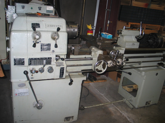
Next of course would be the real test – hooking the lathe up to the idler and seeing if I could get the lathe spinning. This was pretty simple – just attaching a few more wires. Once I had the idler spinning and powered again, I turned on the disconnect on the lathe, switched the power to ‘on’, made sure I didn’t have the carriage or cross-slide in feed mode, and moved the lathe’s control level to ‘forward’. The contactors in the lathe’s power panel clattered and buzzed as the ammeter on the panel jumped around on the far end, attesting to the volume of electrons tearing through the system. The giant chuck began turning, and the clatter died down, leaving only the whirr of properly meshing gears and the low growl of the machine’s motor. Yes, it was alive.
awesome post!
I love your write up and appreciate mention of my name!
I also must add, that my dual idler RPC always runs both idlers. I start one, then I start another, and only then I have output power.
have you wired TWO idles in parallel to power ONE machine? ? say, 10 HP in parallel with 7.5 HP to power a 15 HP machine… ?
Well, I haven’t actually hooked them up that way just yet (I’ve only run with the 10HP motor alone so far), but that is indeed the intent. Igor Chudov runs his RPC in exactly that way and it works pretty well.
Hola que tal vi tu articulo y me gusto mucho te agradesería mucho si me pudieras mandar unas fotos del comvertidor de fase y un diagrama para poder construir el mio te lo agradecer mucho gracias.
Paublo – I highly recommend looking through Igor’s information on building an RPC here: http://igor.chudov.com/projects/17.5-Phase-Converter/ There are several links within that have schematics and further info.
Dude, your English sucks. There are huge portions, of your otherwise very nice write up, that are completely incomprehensible, with backwards, implicit double negatives, and illogical phrasing. It’s best to keep your English simple, when you are trying to explain something technical; that’s the first rule in technical writing! It shows you never learnt that and, instead, simply confuse your readers, when otherwise you would come across as brilliant, but because of your poor English, come across as cross-eyed and totally confused.
Jim, thanks for your honest feedback. I admit, this was not my best writing, and I wasn’t totally happy with it 8 years ago. To be fair, I approached it more from a story perspective than strict technical writing in hopes of making it less dull (and because I didn’t fully understand the intricacies of RPCs and didn’t wish to be providing incorrect information about them). Sounds like perhaps I just made things even more confusing as a result!