Support extruder reassembly

After discovering the semi-blockage in the support extruder, I carefully drilled it out with an appropriately sized drill bit and followed up with several pipe cleaners loaded with Mothers Mag & Aluminum Polish. I then carefully cleaned the extruder tube, and pressed on the last spare inlet buffer I have (made from Vespel, again by […]

After discovering the semi-blockage in the support extruder, I carefully drilled it out with an appropriately sized drill bit and followed up with several pipe cleaners loaded with Mothers Mag & Aluminum Polish.

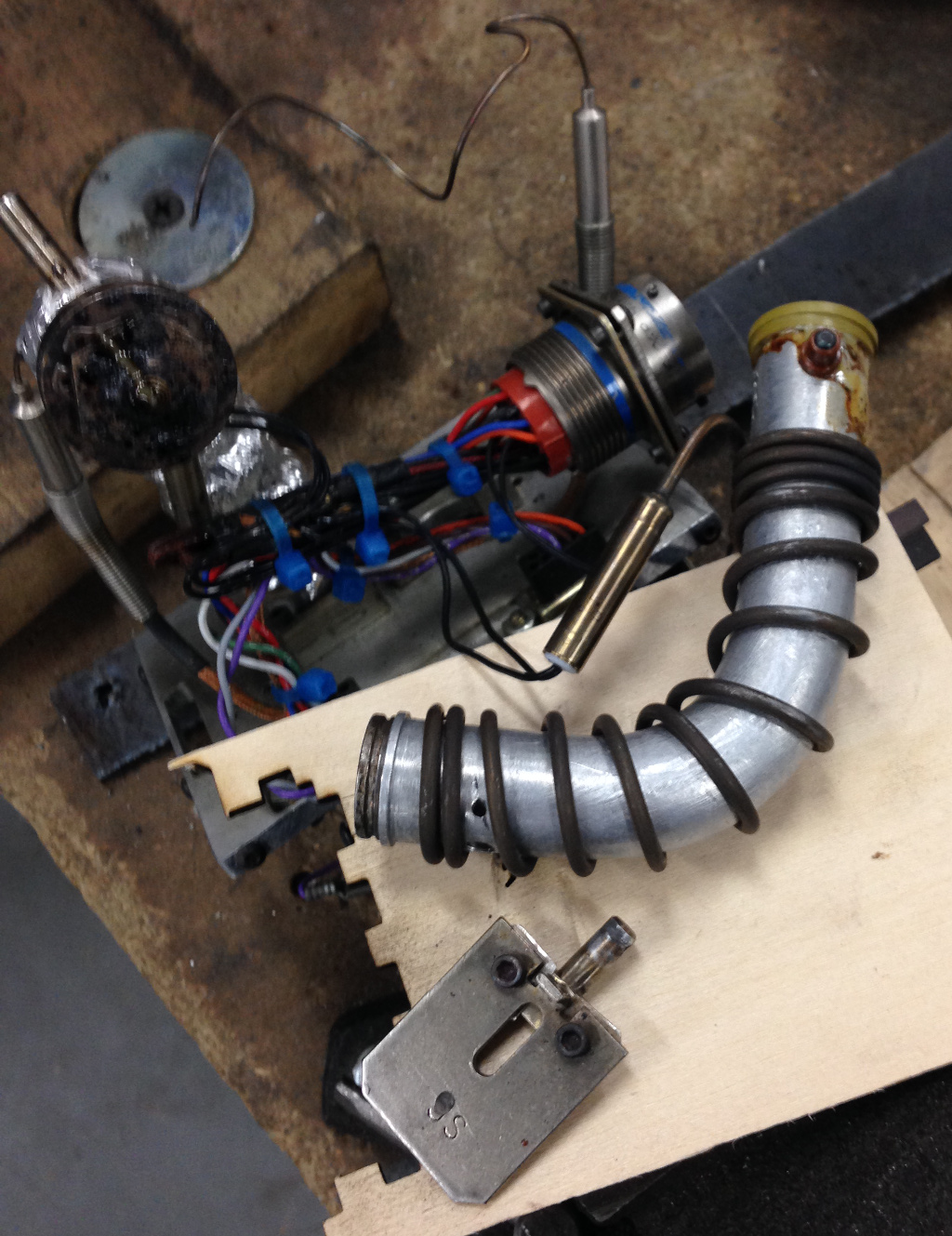
I then carefully cleaned the extruder tube, and pressed on the last spare inlet buffer I have (made from Vespel, again by John).

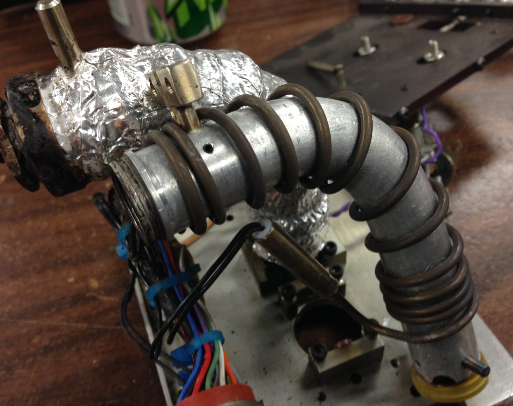
I carefully slid the heater coil back over the extruder (and tried to twist it as much as I could in order to keep it as tight as possible on the tube), re-attached the stud for the solenoid paddle, and re-attached the thermocouple probe.

Then I wrapped the woven fiberglass insulation back around the assembly.

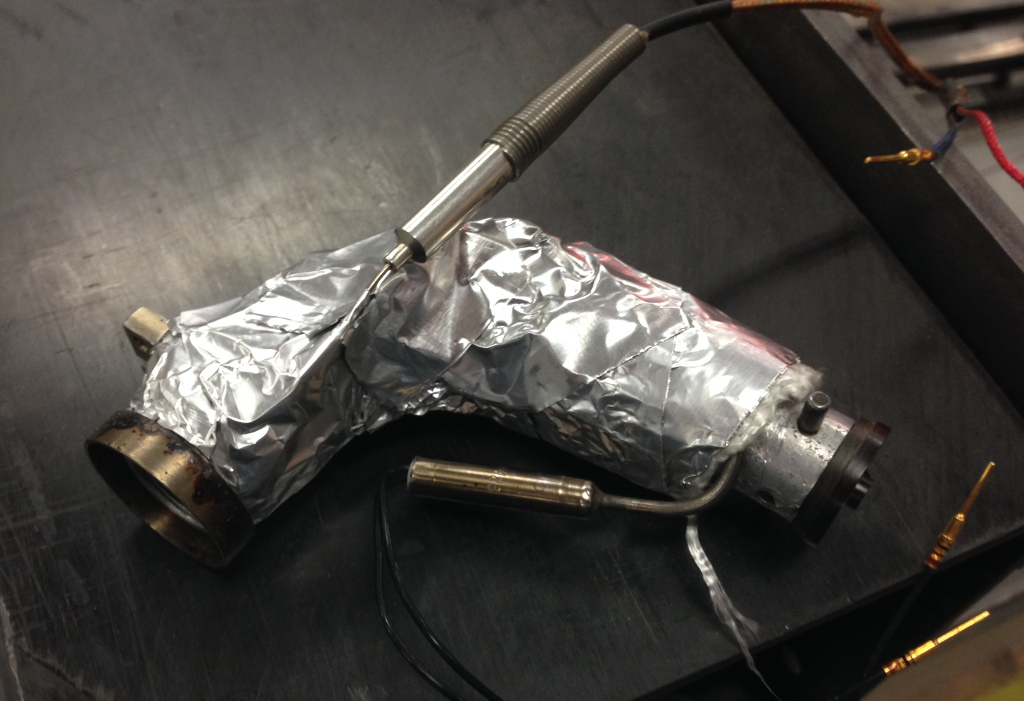
The original foil was unusable, so I tried using plain old ‘heavy duty’ aluminum foil from the grocery store.  It wasn’t as thick, so I doubled it up and did my best to wrap it as tightly as I could (using pieces of 3M high-temperature flue tape to hold it all in place).

The next step was to re-insert the pins for the heater and thermocouple back into the circular connector (I had pulled the pins out in order to more easily re-attach the heater and thermocouple to the extruder tube).  Note that the correct insertion/removal tool is the Amphenol M81969/14-01 – it took me several orders from Mouser to finally figure out the right size.

I then used a few zip-ties to neaten up all the wires.

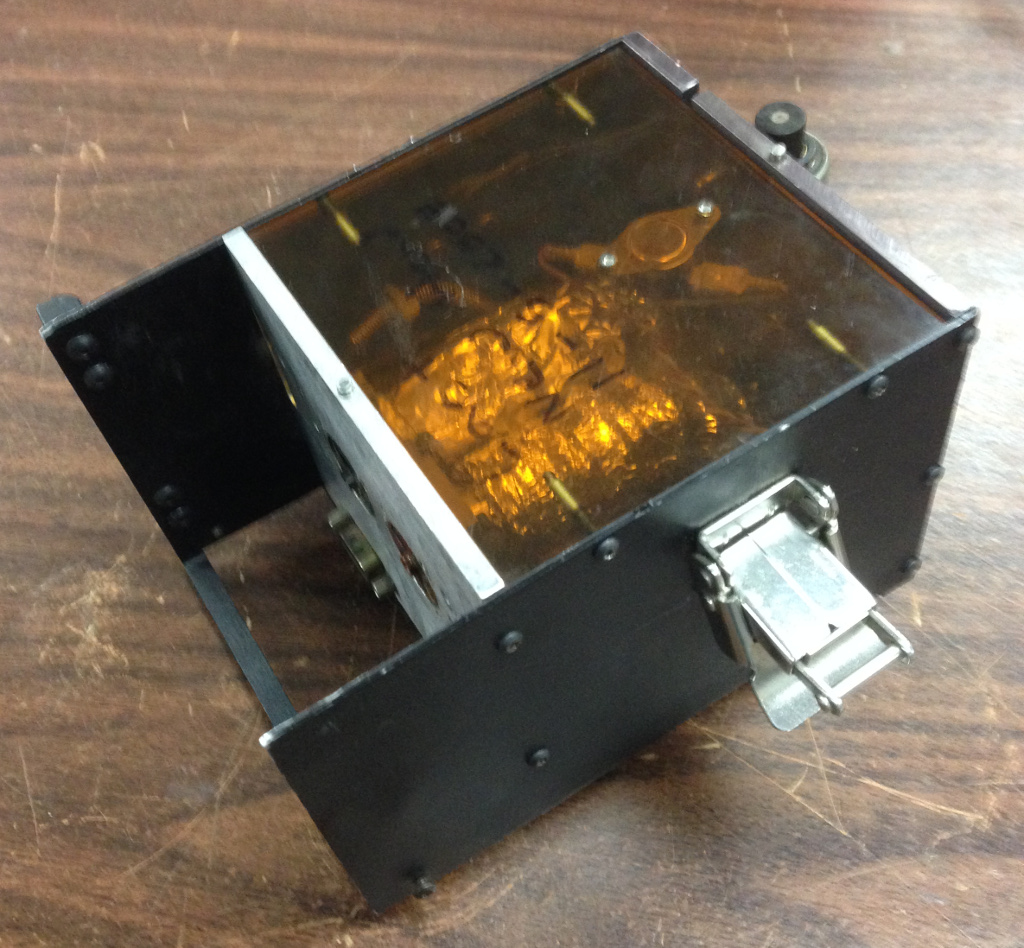
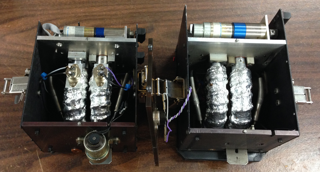
Everything got reassembled back into the housing.

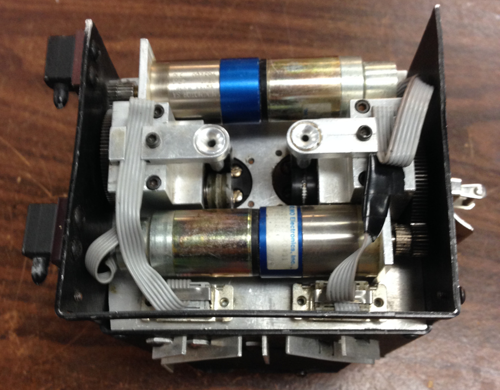
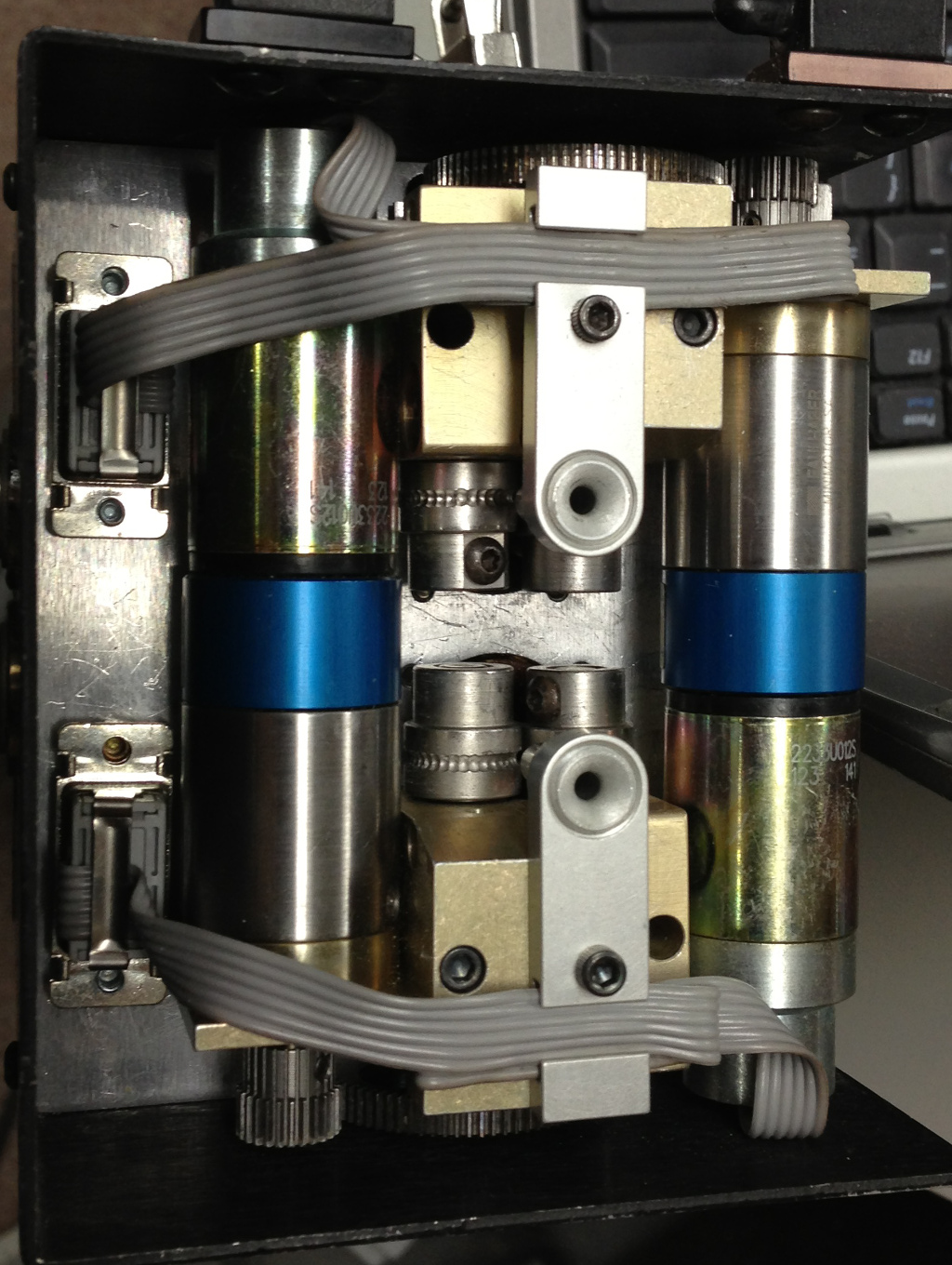
Re-attach the motor drive blocks.

After putting the head back in the printer, I ran a few feet of support filament though the extruder to flush it out.  Things were looking good…  …until I attached the nozzle and tried running more filament through it.  Just as before I started the extruder teardown, it jammed, kinking the filament off to the side between the drive wheels and inlet buffer.  Seeing that the buffer was also now cracked, I said a few choice words and called it quits for the day.

Upon reflection, I figured that the extruder probably wasn’t the issue in the first place (assuming that I had done the rebuild correctly) and that the motor drive block or the nozzle was the culprit.  I removed the motor drive blocks and set the head in the machine so that I could power it up and try feeding the filament through by hand.  I was able to push the ABS filament through pretty easily, but the support filament I could barely budge.  So I removed the support nozzle and put the model nozzle on the support extruder.  Wonder of wonders, I was able to feed through the filament just as easily – the nozzle must be the problem!  I reinstalled the motor drive blocks and sure enough, the support drive was able to feed support filament through the support extruder and model nozzle with no jamming whatsoever.

I’ll try clearing out the support nozzle with a 0.011″ drill bit (even though I know I’ve done so once already), and I believe I have a spare T12 support nozzle floating around in case that doesn’t work.  At least I’ve finally found the core issue and I’ll hopefully have the machine fully functional in only a week or two.  [insert something about ‘famous last words’]

Gunsmithing with a 3D Printer – Part 5

I realized it has been over a year since I last wrote on the subject (though to be fair, it seems it has been about that much time since I’ve written much of anything substantial).  Since I last addressed the topic in March of 2013, the apex of the “3D printed gun” story has been […]

I realized it has been over a year since I last wrote on the subject (though to be fair, it seems it has been about that much time since I’ve written much of anything substantial).  Since I last addressed the topic in March of 2013, the apex of the “3D printed gun” story has been reached, and media interest in the concept has subsided.  Just as promised, Defense Distributed successfully created an entirely 3D printed firearm (save for a roofing nail used as a firing pin), proved the functionality, and released the STL files.

Naturally, I downloaded the files as soon as they were released last May.  Ever since Defense Distributed had stated their goal of designing, testing, and proving the possibility of a 3D printed gun, I had pondered how to actually achieve such a goal.  I had my own ideas in mind, and figured I could probably design something workable in a weekend, but testing and refining the design is something else – CAD is easy, but proving the model is hard.  My own line of thinking revolved around using a .410 shotshell as the intended cartridge, due to its extremely low pressure in comparison with other rounds.  This would have entailed building a fairly large gun with a rather long barrel (over 18 inches so as to not run afoul of the NFA), and would have taken quite a while to print.  As it turned out, DD came up with a remarkably elegant gun, far more refined than what I myself had in mind – something that stayed true to the intent of pushing the limits of 3D printing.  When I say elegant, I mean elegant in the Unix sense – not something that is beautiful to behold in an artistic manner, but something that has raw simplicity and efficiency in design and operation.

DD called their creation the Liberator, an homage to the FP-45 Liberator of WWII, an equally simple, straightforward pistol that was intended to be airdropped into occupied Europe for partisans to use in resistance of German forces.  The DD version is much chunkier in construction, but shares many of the same design intents – a gun that is able to fire a single shot with a centerfire metallic cartridge with as little mechanical complexity possible.

To this end, the Liberator is an impressive piece of work.  It consists of only a handful of 3D printed components:

  • receiver
  • barrel
  • breech block
  • grip
  • hammer
  • trigger
  • 2 hammer springs
  • trigger spring
  • firing pin

Plus a few pins that hold everything together.  Of these, only the firing pin itself is metal and is actually a roofing nail – since the firing pin needs to impact the cartridge primer and deform it enough to crush the compound between the primer’s cup and anvil, material hardness is a key consideration for the firing pin (and is a material property that escapes the current capabilities of FDM printing technology).

Since I had a number of journalists ask me for my take on the Liberator, I decided to print one for myself in order to give an accurate appraisal of the design.  My friend Joe (not his real name) was also interested in building and testing one to make a proper evaluation, so we collaborated on doing a proper test shortly after the design was released.

I opted to use up the rest of my MG47 filament for the various Liberator parts.  Unfortunately, I lost extrusion halfway through printing the receiver:

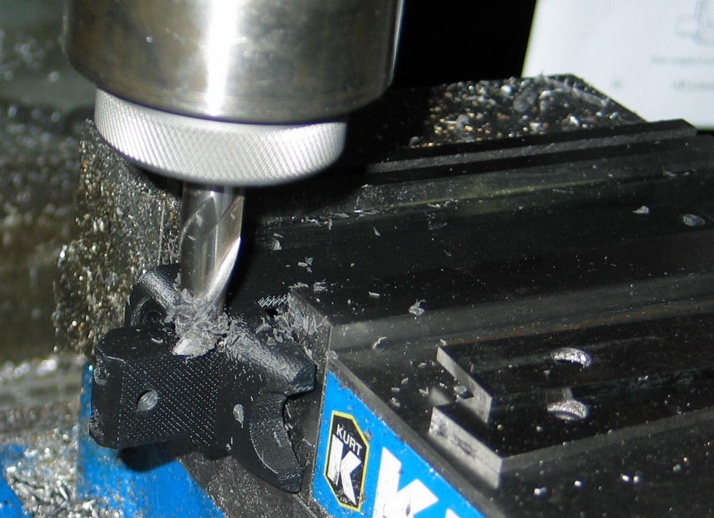
Rather than re-print the entire thing (which was over 30 hours), I decided to place the part in the mill vise and plane off the top, then glue on a replacement top half.
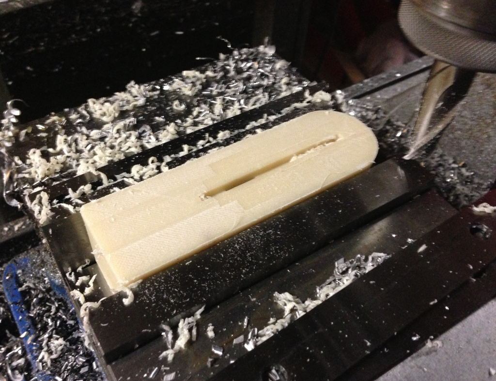
I took the opportunity to also glue in a metal block for compliance with the Undetectable Firearms Act.  I bought some 1″ square steel bar and sawed a piece off the end, then found a little bit of scrap to fill in the sides.  All told, I had 147 grams of steel, which should be more than sufficient to satisfy 922(p) (the specific section of US law codifying the UFA).

Insight is a powerful piece of 3D printing software, and I was able to go back to my sliced version of the receiver and delete all the layers from the file that I had already successfully printed.  This allowed me to print just the upper half of the receiver, and I printed a barrel at the same time for good measure.
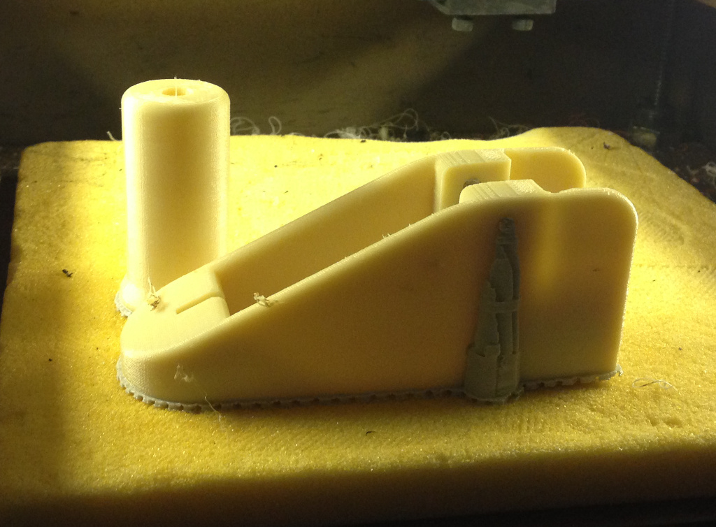
Note that the .STL file for the Liberator barrel that was originally released is a smoothbore with no rifling (just like the original WWII FP-45 Liberator).  This theoretically makes it an AOW (Any Other Weapon) under the 1934 National Firearms Act (NFA).  The definition of an AOW is rather convoluted (and somewhat contested, given U.S. v. Davis), but it is intended as a catch-all category for firearms not otherwise defined by other categories (hence, ‘Any Other’).  A pistol or revolver with a smooth bore is generally considered an AOW, and for an unlicensed individual to make one, they need to submit a Form 1 to the ATF along with fingerprint cards, a passport photo, $200, and a sign-off from their chief law enforcement officer.  In other words, if you want to try printing a Liberator and don’t want a lot of hassle, make sure the barrel has rifling in it to avoid trouble.  Even modern reproductions of the FP-45 Liberator have tiny (and ineffective) rifling grooves in order to remain compliant.

I made sure to add rifling to the print itself, as rifling it afterwards would necessitate equipment that I simply don’t have (but would love to build someday).
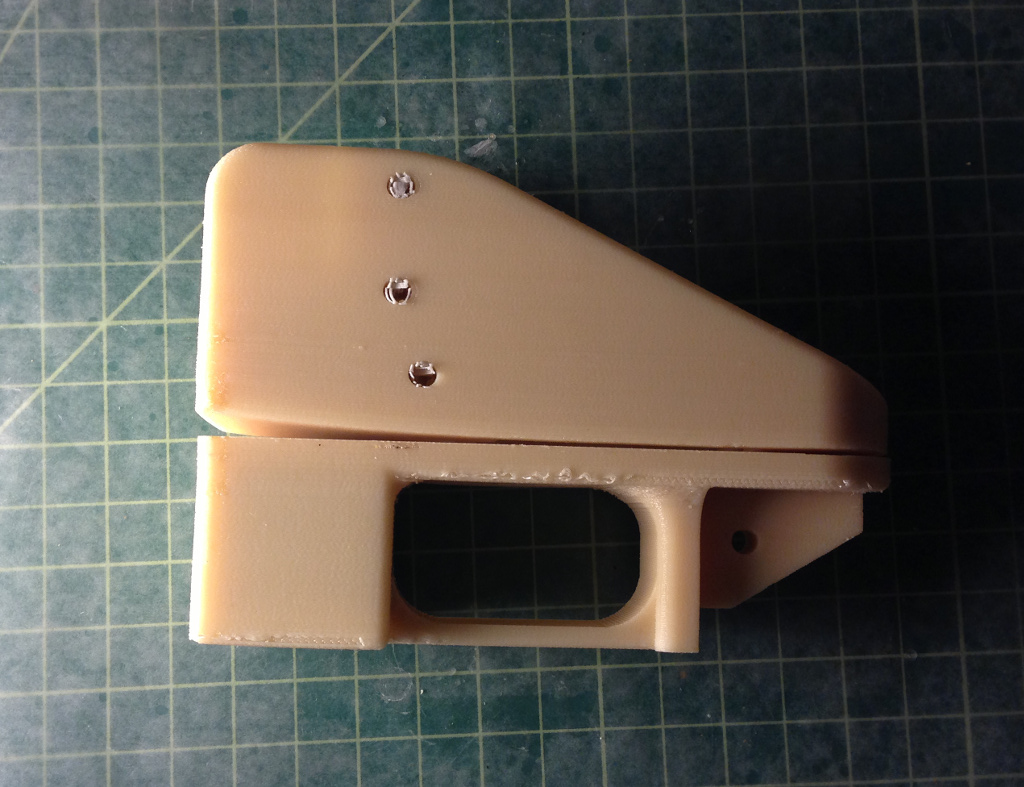
Although the top half of the receiver printed without loss of extrusion, there was still a significant amount of warp on the bottom.  I opted to mix up a batch of epoxy with microballoons and colloidal silica (a thickener) to glue the two halves together.
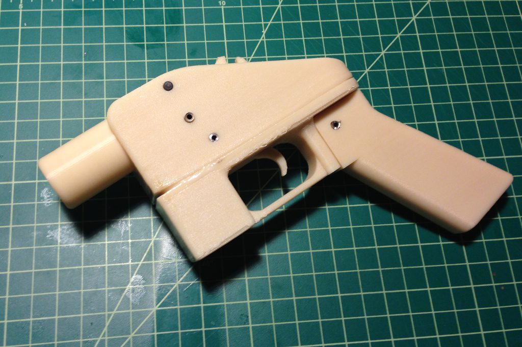
I didn’t actually print the needed pins and just used some spare sections of metal tubing instead.

Meanwhile, Joe used his Lulzbot to create a remarkably robust receiver out of standard PA-747 filament.  He had tweaked his machine to provide extraordinarily dense prints with virtually no porosity.  We decided to test out his version to determine just how well the design works, its durability, and to get some velocity data to determine actual muzzle velocity.  Additionally, news stories on the Liberator seemed to generally claim that a $10,000 (or more) 3D printer was required to print the Liberator.  We wanted to dismiss this notion and show that even a $1000 printer is perfectly capable of printing high strength objects.
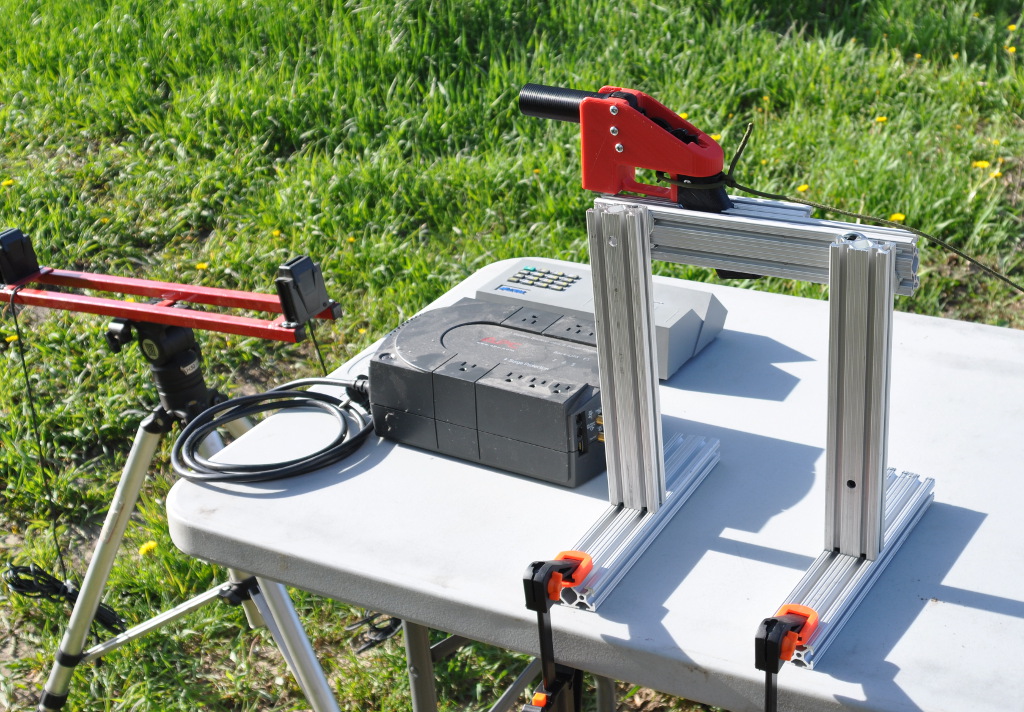
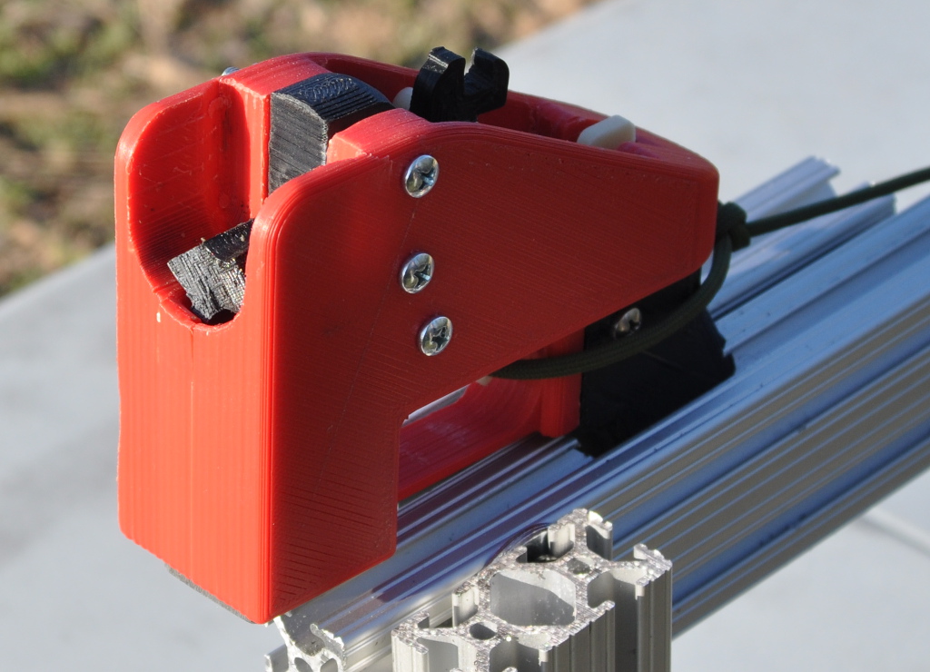
In mid-May of last year, we met up to actually perform the testing.  Our test rig consisted of an 80/20 frame to actually mount the Liberator to, which itself we clamped to a folding table.  In front of the test rig, we set up the sensors for my PACT chronograph (used to measure the speed of the fired bullet).  For safety, we used a 30 foot length of paracord to pull the trigger.  Note also that we used machine screws to actually mount the breech block within the receiver, rather than 3D printed pins.  Additionally, Joe’s barrel was slightly longer than the published Liberator barrel.

We had a great deal of difficulty getting the gun to fire in the first place, making nearly ten attempts to get it to go ‘bang’.  The first issue was getting the sear tail to actually release the hammer, so we replaced the trigger bar with one printed on my machine.  After this, the primer was indeed getting struck, but it did not seem to be igniting – we replaced the springs with ones from my machine as well.  We would wait 30 seconds after each attempt in case there was a hangfire (thankfully we never had one during the testing).  We wondered if headspacing could be an issue, so we pulled Joe’s barrel and put in one that I had printed on my machine.  We also replaced the .380 cartridge we had been using with a fresh one in case it was a dud.
Our next attempt did indeed go ‘bang’, and there was very little of the barrel left in the receiver.  My Stratasys FDM 1600 still has a bit of porosity in its output, and I hadn’t done a solvent vapor treatment on the barrel as was recommended by Defense Distributed.  Also, the round was a very tight fit and had to be pressed into the barrel – it’s possible that the bullet became dislodged, seating further down within the case and causing higher pressures when fired.  While the barrel was destroyed, we finally achieved primer ignition, so we put Joe’s barrel back in and continued testing.
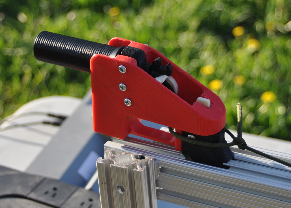
With things finally working (if not smoothly), we proceeded to fire off as many shots as we could manage during the available sunlight.  Here’s a short video of the successful shots made: Lulz Liberator testing video

The video hints at some of the issues we ran into during testing.  We didn’t have the retainer for the firing pin installed, so the firing pin would rocket out the back during every shot.  We used a piece of masking tape on one attempt (you can see it fly up after the shot) to try and keep the firing pin in place, but the hole punched through the tape shows that this did not work at all.  We only had one roofing nail, but fortunately Joe happened to have along extra machine screws that he used for assembly and was able to fashion a replacement firing pin each time by cutting and filing it with a pocket multitool.  We had to make the firing pin longer each time as well, since each subsequent shot increased the headspace, with the cartridge becoming seated further and further down the barrel each time.

The 3 screws holding the breech block in place also became noticeably bent as testing continued, so we replaced them halfway through.

Here’s what the Lulzbot printed barrel looked like after its first successful firing.  The cartridge has actually been pushed back a bit (hence pushing back on the breech block and bending the retaining screws as noted).  You can also see white spots forming (known as crazing) as a result of the internal stress.  Finally, the primer has been pierced, allowing gas to erupt out the back of the cartridge, which is an undesirable behavior.  However, this is not a fault of the Liberator’s design, but a side effect of using a roofing nail or ‘field expedient’ machine screw – the sharp nose of the nail or screw actually punctures the primer cup, whereas proper firearm firing pins actually have a carefully rounded nose so that they dent but do not pierce the primer.  In fairness, however, pierced primers are not a great concern on a disposable firearm such as the Liberator or its WWII ancestor.  Continually piercing primers will allow the hot gases to erode the bolt face, firing pin hole, firing pin tip, etc. in a conventional firearm, but for a disposable gun designed to operate only a few times, this is admittedly a minor design quibble.

One thing the photo does not really indicate is how firmly the brass case is actually stuck inside the barrel.  In a conventional metal barrel, the brass does expand somewhat during firing, which is actually beneficial in sealing the case to the chamber walls in a process known as obturation.  The brass relaxes slightly as the bullet exits the barrel (which allows the internal pressure to drop back down to atmospheric levels), but since ABS plastic is much lower in strength than steel, the brass case expands greatly in the Liberator making conventional extraction all but impossible.  In our case, we needed to use a hex wrench and a rock to beat the expended cartridge out of the barrel.
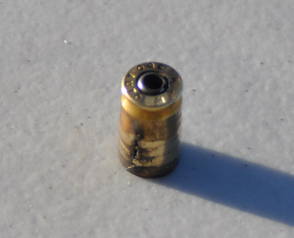
Unsurprisingly, the walls had expanded so far that the case had actually split.

More surprising to us, though, was the fact that the barrel bore looked entirely unscathed (not only by the projectile, but by the hot propellant gases).  The photo really doesn’t show it, but in looking down the bore, the finish appeared just the same as in the unfired state.  Both Joe and I presume that there is so much bore expansion during firing that the bullet itself isn’t even touching the rifling.  Granted, the rifling would have done almost nothing anyhow (a copper jacket is still much harder than ABS plastic).

We only managed to record two shots with the chronograph (we weren’t using skyscreens, and they probably would have helped).  The captured velocities were 498.2 and 465.1 fps, for an average of 481.7 feet per second (146.6 m/s).  By comparison, the very same round fired out of a conventional .380 pistol will be well over 900 fps.  Consider that kinetic energy (or ‘muzzle energy’ in firearms parlance) increases as the square of velocity, and the difference is quite dramatic – the Liberator only achieves a muzzle energy of 49 foot-pounds, or roughly a quarter that of what a standard .380 pistol provides.  By way of comparison, a major league fastball delivers twice as much energy, and one person has actually died as a result of being struck with such a pitch (yet a year later, despite proclamations of mayhem and anarchy in the press, there have been zero deaths or even injuries from 3D printed guns).  In the end, then, the Liberator is not at all a weapon of physicality, but a weapon of philosophy, able to challenge preconceived notions regarding governmental control over the sharing of information.  Which, whether you agree or disagree with his views and actions, is precisely what Cody Wilson set out to accomplish in the first place.

Somewhat unsurprisingly, only a few days after DD posted the .STL files for the Liberator on their site, the US State Department sent a letter to Cody, demanding takedown of the Liberator files and 9 other designs that had been posted on Defense Distributed.  The authority for this stems from ITAR, the International Traffic in Arms Regulations, which controls import and export of defense related articles, including information related to such items.  That acronym may ring familiar to old hands of the internet, as it is the very same statute under which the US government blocked export of Phil Zimmermann’s PGP encryption software in the mid-90s, which saw Phil under criminal investigation for “munitions export without a license”.  While the case against Phil was eventually dropped (and Cody/DD have not been actually charged with any wrongdoing), the parallels are striking.  Like Phil’s case, it will undoubtedly be many years before the issue is resolved.

What struck me oddly about the State Dept. letter were the 9 other designs listed as takedown targets.  In my opinion, these were picked entirely at random in a perfectly transparent attempt to hide the fact that the Liberator files were in fact the sole items of interest.  Specifically, item 6, “Sound Moderator – slip on” was actually designed by noted RepRap contributor (and airgun enthusiast) Vik Olliver and is still available on Thingiverse.  If this was truly an ITAR violation, then why did the State Department not do anything when Vik originally ‘exported’ the file from New Zealand to Thingiverse servers in the US, and why has Thingiverse/Makerbot/Stratasys not received their own ITAR takedown letter for continuing to host this design?  I could opine a great deal more on the topic, but since I attempt to limit my blog writing to technical matters, I’ll curtail my musings.

Other interested people have printed their own versions of the Liberator as well – mashable.com has a superb 8 minute documentary called “I Printed a 3D Gun“, which I highly recommend watching.  Travis Lerol (who has also experimented with printing AR lowers on his 3DS Cube) attempts to give his own Liberator a try, but it fails to ignite (spoiler alert).  Travis tells me that he has since managed to get a round to fire, though it took about 200 attempts.  A number of design remixes of the Liberator concept have also been posted online, though very few (if any) have actually been printed and tested.

I was very honored to be asked by Professor Hod Lipson to make a presentation at the Chicago Inside 3D Printing conference on the topic of 3D printed firearms on July 11.  I was scared stiff to do any sort of public speaking, but thankfully there weren’t many people in the audience, and I had a few friends in attendance for moral support.  I’m very glad I attended, as I was able to chat with so many notable people in the field – not only Hod Lipson, but Avi Reichental (of 3D Systems), Scott Crump (of Stratasys), Scott McGowan (of Solid Concepts) and especially Ralph Resnick (of NAMII) – thanks to you all for your time and attention.  Chatting with Scott McGowan and some of the other folks from Solid Concepts was especially interesting, given that only a few months later, Solid Concepts would release their own 3D printed gun, the 1911 DMLS.  As a fan of John Browning‘s entire portfolio of work (and especially the M1911 pistol), I was thrilled to see such an iconic, century-old design recreated with cutting-edge technology.  Solid Concepts is now actually selling the 1911 DMLS in a limited run of 100.  While I wish I could afford one as a collectible (Scott, if you have an extra, please drop me a line!), I’m simply happy to see the whole 3D printed gun media story finally reach its logical conclusion: 3D printing is simply another manufacturing technology, and its application to firearms is no different than the development of milling machines, investment casting, CNC, polymers, and on and on.

Addendum: I had initially wanted to cover much more of the work done in the past year by others exploring the intersection of gunsmithing and 3D printing, but this post took long enough to write as it was.  Fortunately, Andy Greenberg (who interviewed Joe and me for several stories last year, and is a superb technology reporter) has an excellent rundown of the various designs being experimented with by FOSSCAD.
Well, there’s your problem…

Since my previous post on the stubborn clog on my Stratasys FDM 2000 support extruder, I made a rather shocking discovery.  But first, what I managed to accomplish before said discovery… The first step was removing the Torlon inlet buffer from the extruder tube.  John‘s inlet buffers are a very nice tight fit to the […]

Since my previous post on the stubborn clog on my Stratasys FDM 2000 support extruder, I made a rather shocking discovery.  But first, what I managed to accomplish before said discovery…

The first step was removing the Torlon inlet buffer from the extruder tube.  John‘s inlet buffers are a very nice tight fit to the tube itself – unfortunately, removing it pretty much requires destruction as a result (sorry, John!).  I figured I could just break it off, but I’d be left with the ‘nipple’ of the inlet buffer still embedded in the tube.  So I used a heat gun to warm up the tube to loosen the material that had leaked out between the tube and inlet buffer while trying to twist off the buffer itself.

Apparently I got things a little too hot, as my gloved hand left imprints in the sides of the Torlon buffer when I finally broke it off.

Unfortunately, I also left a good bit of Torlon stuck inside the inlet, just as I had feared.  At this point, I stuck the extruder tube in a jar of MEK for a good long time and sloshed it around every so often to help soften up the material still inside the tube.  I also occasionally would use a pick to dig out chunks of the Torlon.

My plan at this point was to model the extruder tube in CAD so that I could conceivably machine a replacement in case this one was entirely ruined by internal buildup, gouges, or some other problem.  Alan C. was kind enough to share his FDM 2000 nozzle model and drawing, so I didn’t need to do any work on determining the nozzle threads.  I’m guessing that the threads are actually 9/16″-24 rather than 14.22mm-24tpi, but Alan used a CMM in doing the reverse engineering and his custom made nozzles work perfectly, so who am I to argue with success?  I also noticed that on my 2000’s support nozzle, the central 0.154″ protrusion on the back side of the nozzle actually sticks out by a few thou, whereas Craig noted his is dead flat with the outside ring surface.  There may have been some loose tolerances at work during manufacturing, especially in light of what I found on the extruder tube.

When using some short lengths of wire (old solid core phone wire worked well) as a pseudo pipe cleaner to push/pull out softened polymer goop from the hole that runs through the center of the extruder tube, I noticed something rather odd – the wire would tend to ‘catch’ when I pushed it through from the nozzle end.  It was almost as if there were a constriction in the extruder tube.  After digging out the last bits of Torlon from the inlet side, it still looked like there was some buildup on that end of the extruder.

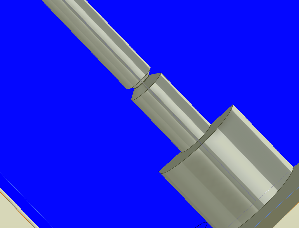
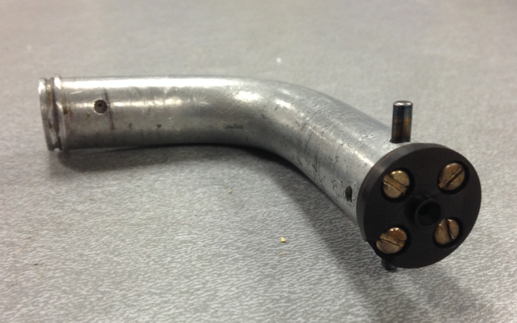
After trying to clean it up further with a pick, and looking at it through a lighted magnifying lens, it became quite clear to me that it wasn’t buildup at all, but aluminum – the extruder tube was poorly made in the first place!  Here’s an image showing exactly how this extruder tube would appear if you sliced it in half:

The extruder tube appears to have been turned on a lathe before having the 90 degree bend done, with the central hole having been drilled through from each end (1/16″ drill from the nozzle end and 5/64″ from the inlet end as best as I can determine).  Apparently one of the holes was drilled just a few hundredths of an inch too shallow, leaving a nice conic restriction just past the inlet.  No wonder the blasted contraption had been jamming like crazy!  Pushing a .05″-ish diameter wire though the fully functional model extruder showed that there was no such restriction.  I can’t think of a single reason why you could conceivably want such a restriction in the first place, so I can only assume that this was extremely poor quality control on the part of Stratasys (apparently the horror stories of people returning malfunctioning heads for replacement only to get back used heads with just as many problems are not at all unfounded).  I’m at once really disappointed in the manufacturer yet relieved that the problem and fix is so blindingly simple.  My solid model probably won’t be needed after all as reference for creating a new hot end, but in case it would be useful for anyone else, here’s the .sldprt as well as an IGES model and a measurable eDrawings .eprt:  FDM2000 heater tube (includes the manufacturing defect just in case I’ve been entirely wrong)

Now, where did I put my number-sized drill set….

Happy Valentine’s Day

I never got around to giving Frankie the manual binder for his Stratasys FDM 2000 because I’m an information packrat and wanted to scan it in for reference.  He had a talk scheduled this week at UWM, and I figured I’d drop by for the presentation and finally give him the manual.  As long as […]

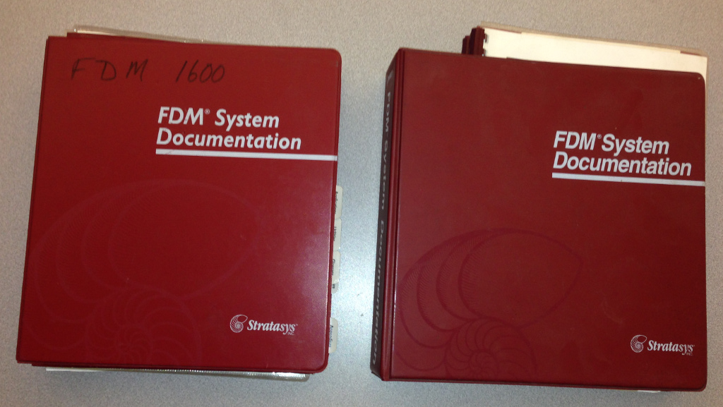
I never got around to giving Frankie the manual binder for his Stratasys FDM 2000 because I’m an information packrat and wanted to scan it in for reference.  He had a talk scheduled this week at UWM, and I figured I’d drop by for the presentation and finally give him the manual.  As long as I was scanning, I finally scanned the entirety of my own FDM 1600 manual.  The fruits of my labors are here for anyone with an old FDM 1600 or 2000 that they need a manual for (though much of the information probably applies to other models as well):

FDM 1600 Manual

FDM 2000 Manual

Quickslice Training Manual v6.3

Insight Training Manual

Speaking of Frankie, he’s been up to some amazing work lately.  In December, Pete forwarded an inquiry to the Milwaukee Makerspace from a local mother whose 8 (almost 9) year old daughter was born with only partial digits on her right hand.  She had seen the Robohand video and asked Santa if she could have a new hand for Christmas.  (sorry, that gets me a little teary-eyed right there.)  A bunch of us immediately offered to help in any way possible (I have a small supply of medically approved, gamma-sterilizable P500 filament that would be perfect for this application), but Frankie absolutely tore into the project with unbridled enthusiasm.  He’s been working with others at UWM to develop a truly custom prosthetic for Shea, and has actually introduced it into a course curriculum this semester (they’ll be creating hands for other area kids in need and developing a ‘how-to’ guide for these DIY prosthetics).  Frankie is still developing the hand for Shea, but I can’t wait to assist in my own tiny way (we have some ideas in mind for customization that should go over well with the end user).  If anybody out there has any surplus P500 ABSi that they would like to get rid of, please leave a comment – we can definitely put it to good use.

This past weekend, Shea visited Frankie’s lab and got to try on a prototype hand for the first time (in her own color choice, no less), and after a few tries, was able to pick up objects with it.  She also discovered to her delight that she was able to make a ‘big heart’ with her fingers:

Excuse me for just a moment, I seem to have something in my eye…  *sniff*  For more information, check out the E-Nable page.  It’s inspiring, humbling, and just kind of amazing to see what 3D printing is making possible.

Capacitor replacement

Dad’s large screen TV has been having issues for quite a while, taking an increasingly long time to finally power up, culminating in a failure to power on at all.  He discovered that this is a fairly common issue with that model (Samsung LN-T4061F), and that the root cause is failing capacitors in the voltage […]

Dad’s large screen TV has been having issues for quite a while, taking an increasingly long time to finally power up, culminating in a failure to power on at all.  He discovered that this is a fairly common issue with that model (Samsung LN-T4061F), and that the root cause is failing capacitors in the voltage regulator section.  This reminded me that I still had to fix a friend’s Slingbox with the exact same issue, so it was off to the Makerspace to do some desoldering and order replacements.

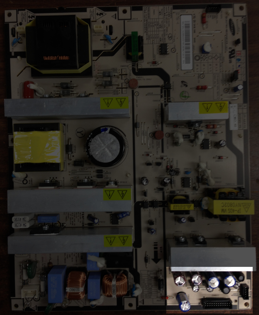
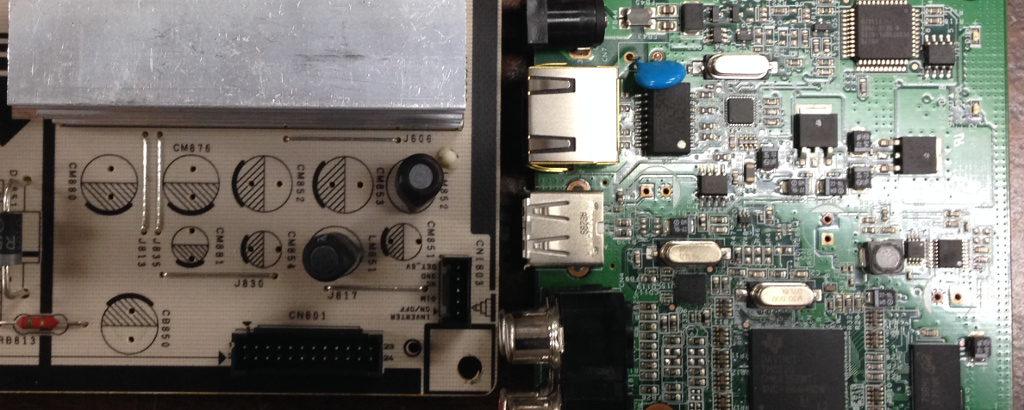
The highlighted area shows the problematic caps on the board.  I have to say, this is one of the nicest PCBs that I’ve ever seen – all of the components are clearly labeled, test points are called out, saw cuts in the board provide additional voltage isolation, etc.  In an age where including circuit diagrams with a piece of electronics equipment is but a distant memory, could this board have actually been created with diagnosis and repair as design goals rather than the all-too-common approach of repair by replacement?

Left to right, top to bottom, the capacitors are:

CM880: Sam Young KMG 1000uF 25V 105°C (replaced with Digi-Key 493-4504-1-ND)

CM876: Sam Young KMG 1000uF 25V 105°C (replaced with Digi-Key 493-4504-1-ND)

CM852: Samsumg VMA 2200uF 10V 105°C (replaced with Digi-Key 493-4495-1-ND)

CM853: Samsumg VMA 2200uF 10V 105°C (replaced with Digi-Key 493-4495-1-ND)

CM881: Sam Young LXV 47uF 50V 105°C (replaced with Digi-Key 493-4512-1-ND)

CM854: Sam Young LXV 47uF 50V 105°C (replaced with Digi-Key 493-4512-1-ND)

CM851: Sam Young LXV 47uF 50V 105°C (replaced with Digi-Key 493-4512-1-ND)

CB850: Samsung VDE 1000uF 10V 105°C (replaced with Digi-Key 493-4494-1-ND)

The two components (LM852 and LM851) that look shrouded in heat shrink tubing are inductors and don’t need replacement (inductors are just coils and unlike electrolytic capacitors, don’t have electrolyte to evaporate away over time).  Obviously, the brown corrosion at the tops of CM852 and CM853 point to leakage on these caps, but it’s prudent to replace them all.

On the Slingbox I found:

CB18: 220uF 25v 105°C (replaced with Digi-Key 493-13386-ND)

CB45: 470uF 16v 105°C (replaced with Digi-Key 493-4499-1-ND)

CB43: 470uF 16v 105°C (replaced with Digi-Key 493-4499-1-ND)

If you look up the specific Digi-Key part numbers I listed, they’re all 125°C rated caps at the next highest voltage rating I could find.  I’ve heard that the rule of thumb is to just bump the voltage rating when replacing failed capacitors, but I figure upping the thermal rating in addition can’t hurt at all.  A bulb-type desoldering iron made quick work of removing them from the boards.

After waiting a few days for my Digi-Key order to arrive, I was ready to install the replacements.  I started with the Slingbox board, which had ample room for the larger replacement caps.  However, the solder pads were hesitant to actually take on any new solder.  By comparison, the Samsung board took solder on the pads with aplomb.

In comparison to the Slingbox board, the new caps on the Samsung board had to be shoehorned into place.  This was expected, though, as an increase in voltage rating or in thermal rating generally incurs an increase in package size as well.  I’ll happily take a board that may be less aesthetically populated in exchange for having it able to withstand a nuclear winter, zombie apocalypse, or Justin Beiber album.  While the initial failure of the Samsung board is a bit disheartening, I’ll still give Samsung praise for a superb, easily repairable PCB.  So to the unknown engineer(s) who toiled away on the design of IP-231135A to make it better than ‘good enough’, dad says ‘thanks’.

3DS Cube cartridges

A friend sent me a used filament cartridge from his 3DS Cube a while back, as I had heard that they are ‘chipped’ similarly to Stratasys cartridges. Sure enough, there’s a 1-wire chip on one corner of the cartridge. Opening the cartridge requires almost destroying it.  The two halves are actually solvent welded together, and […]

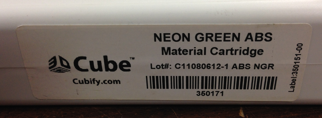
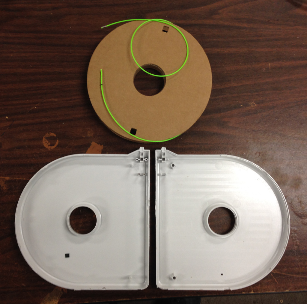
A friend sent me a used filament cartridge from his 3DS Cube a while back, as I had heard that they are ‘chipped’ similarly to Stratasys cartridges.

Sure enough, there’s a 1-wire chip on one corner of the cartridge.

Opening the cartridge requires almost destroying it.  The two halves are actually solvent welded together, and inside is a ridiculously small cardboard spool of filament.  One user determined that the printer will only allow 320 grams of filament to be used before declaring the cartridge to be empty.  At $50 per cartridge, this isn’t quite as bad as Stratasys pricing, but it’s still insanely expensive for what is targeted as being a hobbyist machine.

With the Stratasys cartridges at least, the cartridge is sealed with a gasket all the way around the edge where the halves mate, and the interior is packed with desiccant packets.  No such environmental protection exists on the Cube cartridge – there’s an open hole in one side (with a threaded brass insert whose purpose escapes me), and there’s an o-ring on the exit to keep the filament in place (if you accidentally pushed the filament back into the cartridge, you would need to break open the cartridge to fish out the end).

Unlike the Stratasys cartridges, there is no PCB board at all – the tiny 2-wire EEPROM is just a tiny SFN package measuring only 6mm on a side.  Unfortunately, I actually broke it in half when busting open the cartridge, so I can’t actually attempt a read on it.  But at least I verified that it is in fact a Maxim DS28E01 1Kb (that’s kilobit, mind you) 1-wire EEPROM.  Oh, and it’s SHA-1 protected, just as I’ve heard that the Stratasys uPrint cartridge EEPROMs are.  I’ve read that the printer can be tricked into running generic filament by leaving the EEPROM in place and simply telling the machine “that’s okay, continue printing anyway” when it alerts that filament is out.  Newer firmware versions are said to eliminate this workaround but it appears that somebody has managed to break the cartridge encryption.  They created (or at least claim to have) a USB controlled dongle to fake full cartridges so that bulk filament can still be used no matter what the firmware version.  At $167 for the very cheapest version, though, I’d be inclined to just tear out the original electronics and run everything with a RAMPS board if possible.

The Stratasys extruder clog from hell

When I last wrote, I was dealing with a Stratasys FDM 2000 head solenoid that just wasn’t working.  Well, I managed to get a replacement (thanks, John!) and sent the original off to a company in the Chicago area that rebuilds old automotive starter solenoids of that same ‘crimped can’ construction.  I think one of […]

When I last wrote, I was dealing with a Stratasys FDM 2000 head solenoid that just wasn’t working.  Well, I managed to get a replacement (thanks, John!) and sent the original off to a company in the Chicago area that rebuilds old automotive starter solenoids of that same ‘crimped can’ construction.  I think one of the leads simply became detached from the coil winding, which should in theory be a simple repair.  But having zero experience in that realm, I’m happy to let an expert take a crack at it first.

That lead on the left looks a bit suspect...

The solenoid from John works like a champ, so it was on to the next problem – a persistent clog in the support extruder.  I found that I could extrude support material happily enough if I removed the support nozzle, and I did see a few specks of crud get flushed out from the support side as I ran foot after foot of filament through it.  I also cleared out the nozzle itself with a 0.011″ drill bit in a pin vise, just as I’ve done on my 1600.  Still, this didn’t seem to help much.  I could extrude a little bit of material out of the nozzle, but after perhaps 10 seconds or so, the material would stop coming out of the nozzle and would backflow out of the inlet buffer.  I figured that there must be some sort of blockage still in the extruder, so I purchased some soft brass wire and the teeniest wire brushes I’ve ever seen from McMaster-Carr.  I removed the nozzle from the support extruder as well as the support motor drive block, heated the support side to the normal operating temperature in the printer, then quickly removed the head and ran about a foot of the brass wire through the extruder to drag out as much of the soft support material as possible.  I also removed the inlet buffer, but forgot that they actually have a tip that presses into the metal tube that serves as the ‘hot end’, thus rediscovering the issue that Rob @ Incredilution had found when attempting repair on his head.  Namely, I broke off the tip in the heater tube.  Naturally, I shrugged and put the inlet buffer back in place after cleaning, figuring that the break wasn’t a big deal.  I was mistaken – when I heated the head back up and tried feeding support material in once more, the material backflowed out of a heretofore undetected hairline crack on the back face of the buffer itself.

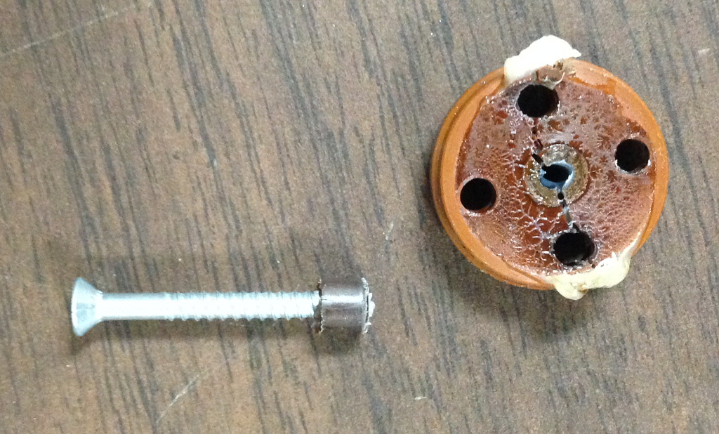
A hairline crack runs from the lower left screw to the upper right screw, and plastic actually leaks out of this crack when the filament is fed in

I removed the inlet buffer once more and used a screw to extract the broken tip from the heater tube.

Fortunately, John had machined some replacement inlet buffers some time back from some scrap Torlon that I had sent him, and I’m glad I had one on hand.

Unfortunately, even after thoroughly scrubbing the support extruder, things were now worse than ever, and I now get material backflowing out of the inlet buffer without even a nozzle attached.  I’m somewhat at a loss to explain why this might be, but the best I can figure is that running the brass wire and mini wire brushes through the extruder might have scratched the interior surface, causing sufficient friction to keep the soft plastic from extruding out the end.  With that possibility in mind, I figured I needed to fully tear down the head for a deeper look.

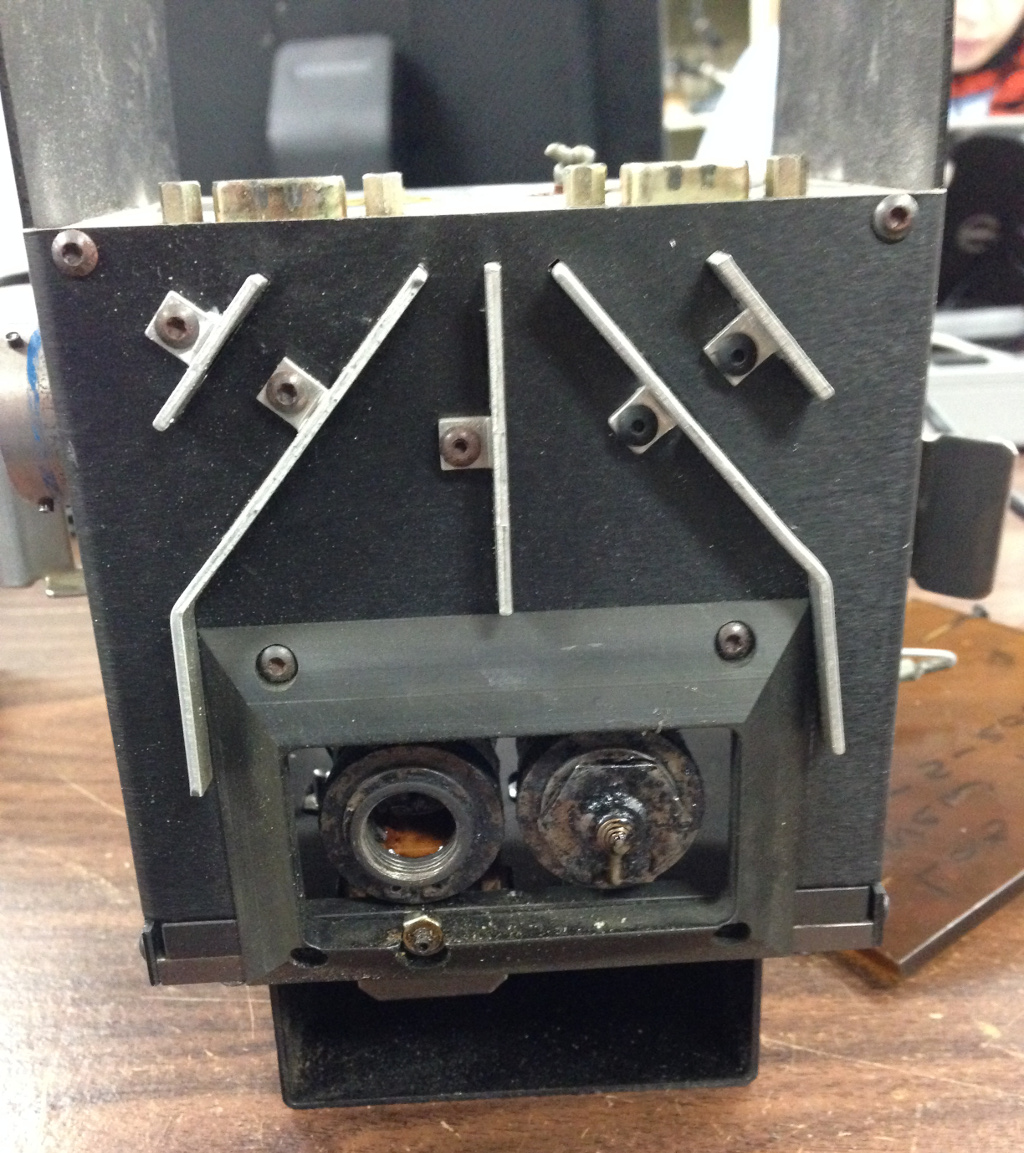
Here’s a look at the bottom side of the head with the bottom shroud removed showing the vanes that direct cooling air over the nozzle tips.

With the exterior shell full removed, we have a good look at the internals.

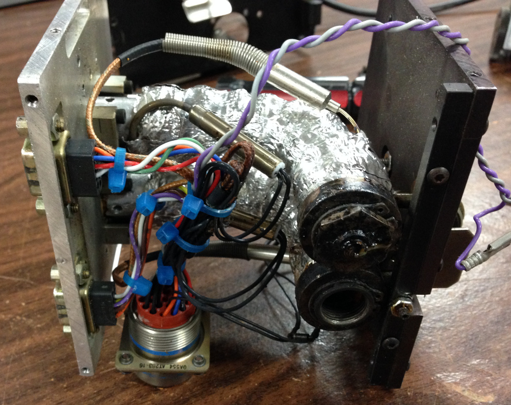
Here’s the bottom side of the head.

The thermocouple runs right into the end of the melt chamber.

Removing the aluminum foil outerwrap reveals the fiberglass insulation wrap.

With the fiberglass out of the way, we can see the heater coil wound around the melt chamber.

I first had to use a small punch to drive out the roll pin securing the solenoid paddle to the extruder.

Then I could finally snake the extruder free of the heater coil.  I had tried to slip the coil over the end, in the hopes of easily replacing it, but replacing any of this is going to be tough work.

And here it is – the ‘hot end’ freed from its overwrappings.  Now I just need to remove the inlet buffer and give the tube a solid cleaning to try and figure out what is causing the clog.

A tale of two Stratasyses. Stratases? Stratasi??

Early this year, I managed to get a good deal on a Stratasys FDM 2000 from the guys over at the Cincinnati hackerspace, Hive13, making this the third 3D printer I’ve purchased (and the second I’ve sold to Frankie for use at the DCRL, but more on that later). What makes it particularly nifty is […]

Early this year, I managed to get a good deal on a Stratasys FDM 2000 from the guys over at the Cincinnati hackerspace, Hive13, making this the third 3D printer I’ve purchased (and the second I’ve sold to Frankie for use at the DCRL, but more on that later).

What makes it particularly nifty is that it has a soluble support head, which is quite rare for an FDM series machine – most had plain old breakaway suuport heads.  From the start, I had intended to loan this printer to the DCRL, since I’ve been looking for a professional grade FDM printer for Frankie for quite some time – he’s done amazing things with the RepRaps he and his students have built, but there’s nothing like having a machine that runs a separate support material (to say nothing of having a much larger 10x10x10 build envelope).

Once I brought the machine home, I parked it at the Milwaukee Makerspace for a few months so I could give it a checkout and let the other members use it for the time being.  Despite having a great deal of experience with the FDM 1600, the 2000 had me stymied when I tried actually printing with it.  While I was able to get the head spooled up with filament, I just couldn’t get the machine to actually print anything.  Thanks to John Branlund, I found that the issue was the door latch – unlike the 1600, the 2000 has a door latched sensor and will lock the door and proceed with the print cycle only if the user latches the door closed.  With that figured out, I could actually try some printing.

Naturally, a shot glass had to be made for the first print, though it was quite porous, and the few mL of beer I put in it quickly filtered through the bottom.  RapidPrototypeTech, who had previously owned the machine at one point, told me that because this machine has a soluble head, you have to make sure to select soluble support in the software even if running breakaway support.  The difference between the heads is primarily in the motor gearing – a soluble support head is geared much lower from what I’m told.  However, even when trying the exact same job and specifying soluble vs. breakaway support, I still wasn’t seeing any difference in the output – the model extruder simply wasn’t putting out nearly as much material as it should.  Stratasys manuals really don’t provide much help, as such adjustment would be left to a service technician.

While there are some adjustment pots on the main control board (in the lower center of the above photo – the pairs of mustard and blue colored components with screwdriver slotted adjustment screws) that John suggested could be used to adjust the gain for the extruders, I was really hesitant to start messing with potentiometers.  Having disassembled various electronics in my youth, I discovered long ago that messing with such components could very quickly make things stop working properly.  While the years since have taught me that multimeters and oscilloscopes can be used to properly fix such exploration, I still have resistance (pun not intended) to adjusting potentiometers if I don’t know exactly what I am doing.  So I looked around for an alternate method to boost the extrusion rate.

Fortunately, I found what I was looking for in the FDM 2000 Introduction and Reference manuals – pressing Space231 or Space239 on the front keypad allows the model and support material extrusion rates to be modified.  The default values on the machine when I got it were:

Space231 (model material)

1 CAL N MDL 0 (non-ABS model calibration)

2 CAL A MDL -5 (ABS model calibration)

Space239 (support material)

7 CAL N SPT 0 (non-ABS support calibration)

8 CAL A SPT 0 (ABS support calibration)

By trial and error, I adjusted the flow rates until I was getting much better results with printed parts:

2 CAL A MDL 58 (ABS model calibration)

8 CAL A SPT 48 (ABS support calibration)

While this does in fact work, the allowable range for these values is +/- 50, and bumping the ABS model value all the way to 58 results in “NV Memory Error” showing up on the LCD display during powerup.  If anybody knows of a better way to adjust the flowrates (even if it is messing with the potentiometers), leave a comment.  One thing I noticed with the 2000 head versus the 1600 head is that the 2000 head is slightly larger to accommodate larger gearmotors and even dual sets of drive wheels if the material warrants it.  In this case, there isn’t a second set of drive wheels but rather a guide funnel.

The motors have this engraving:

2232U012S

123    141

And this label from the manufacturer, Faulhaber (I first thought the 2233 on the label was a typo, but this appears to be a valid MicroMo model):

2233U012S123  X0800

23/1  134:1  X0431

HES186  KW 28/01

After a few months of fun with the FDM 2000, we finally moved it to the DCRL at UWM where Frankie took ownership of the machine and proceeded to go on a printing spree of epic proportions.  Everyone at the makerspace was sad to see the machine go, but I promised that if I found another it would have a long-term home at the makerspace.  Well, that happened much sooner than expected, and I managed to get another FDM 2000 (this one with a standard ABS head).  I picked it up a few months ago, and finally finished building a mobile base for it the other weekend out of 80/20 extrusion:

I brought the stand to the Makerspace, and we were able to finally wheel it into the 3D printing area:

Since this FDM 2000 has a standard breakaway support ABS head, the motor gearing is a little different.  The support motor itself is a MicroMo with this engraving:

2233U012S

123    466

And a label that says:

2233U012S123  X0431

HES186  23/1  43:1  KW  37/99

The motor for the model material side appears to have the same information, but says 09/97 instead of 37/99 – I’m guessing that may be a date code (week/year format).

For anyone curious, here’s a side-by-side comparison of the heads from my 1600 and the 2000.  The 2000 head on the right has the support nozzle solenoid removed – more on that in a moment:

Note that the actual ‘heater chamber’ is the same size on each head, but the area for the motors is larger on the 2000 head to accommodate a second pair of drive rollers depending on the material the head is designed for.

Note also the shroud on the bottom of the 2000 head – this takes some of the head cooling air and blows it just past the nozzles to cool the freshly deposited filament (at least, this is what I think the idea is).  Interestingly, the FDM 2000 that I passed on to Frankie does not have this shroud, so I’m wondering if it was a later enhancement (or perhaps an idea that was fielded but then scratched)

On powering up the machine, all seems well, except for the support nozzle – specifically, the solenoid wasn’t activating to lower the nozzle.  I took the head out of the machine and found that the wires to the solenoid were pinched between the cover and front plate of the head, possibly shorting them.  Even worse, a multimeter check showed no conductivity between the two leads.  I checked my FDM 1600, and found that the solenoid had about 25.4 Ohms of resistance and was supplied with 24vdc (with a clamping diode to kill the spike that comes off of the coil when de-energized).  While the solenoid on the FDM 2000 head has no identifying information, it appears to be identical to the one on the FDM 1600, which says ‘LISK S-2379’ (I had a bit of info on the 1600 head in on old post).

Even though my previous contact with the Stratasys support department was less-than-helpful, I figured I’d give them a call and see if they might have any spare solenoids.  Unsurprisingly, they don’t have any.  They don’t have anything for the old FDM series machines as of the end of 2011 – FDM owners, we’re entirely on our own.  Stratasys will still give you trade-in credit on your old FDM series machine if you wanted to upgrade, but I don’t think this is a great deal.  These old machines are quite nice in that they’re constructed with a lot of off-the-shelf parts, and are easily modified/hacked.  I think it’s rather telling that there have been a whole bunch of academic papers on 3D printing that use an FDM thousand series machine as the testbed, but precious few papers have been done with the current P-class machines – they are far more proprietary in nature and don’t lend themselves well to experimentation.

At any rate, if Stratasys was a bust, at least I could contact the solenoid maker, G.W. Lisk.  Lisk only makes custom solenoids and doesn’t have any stock offerings, so I gave them a call to see what they could tell me about model S-2379.  Yes, it was made specifically for Stratasys.  It’s a continuous duty 24vdc solenoid, with a coil resistance of 21.6-26.4 Ohms at 25°C.  And that’s about all they could tell me, other than that no, they didn’t have any in stock.  I didn’t ask how much it would cost to have more produced, but I got the distinct impression that it would be greater than one arm and one leg, so I did not pursue that line of inquiry.

In looking around at off-the-shelf solenoid offerings, I’ve noticed that when it comes to 24vdc solenoids, they generally bottom out at around 80-90 Ohms or so, and are much larger in diameter than the S-2379.  The lower resistance results in a much larger power draw and more force, but given that the solenoid operates in a 70°C oven, this derates the performance.  At any rate, I seem to be out of luck in sourcing an off-the-shelf replacement and am investigating whether or not I can have the existing solenoid repaired.

Rotary Phase Converter – Part 3, aka ‘What temperature do electrons burn at?’

When machining the scope mount spacer rings in a previous post, I had been planning to finish them when Max had stopped by one evening.  Simple enough – fire up the RPC and turn on the lathe.  Only thing was, the red ‘start’ button on the RPC was stuck and I couldn’t press it in.  […]

When machining the scope mount spacer rings in a previous post, I had been planning to finish them when Max had stopped by one evening.  Simple enough – fire up the RPC and turn on the lathe.  Only thing was, the red ‘start’ button on the RPC was stuck and I couldn’t press it in.  What the heck?  Being in an impatient, Neanderthal-esque mood (I was hoping Max could take home all the parts for the project that night), I powered down the system and removed the button so that I could hammer it into a variable on/off mechanism rather than being restricted to the single, not-terribly-useful state of ‘off’.  With my ‘fix’ complete, I re-installed the switch in the semi-dangling sheet metal front panel (I plan to fully enclose the whole thing nicely one of these days, honest).

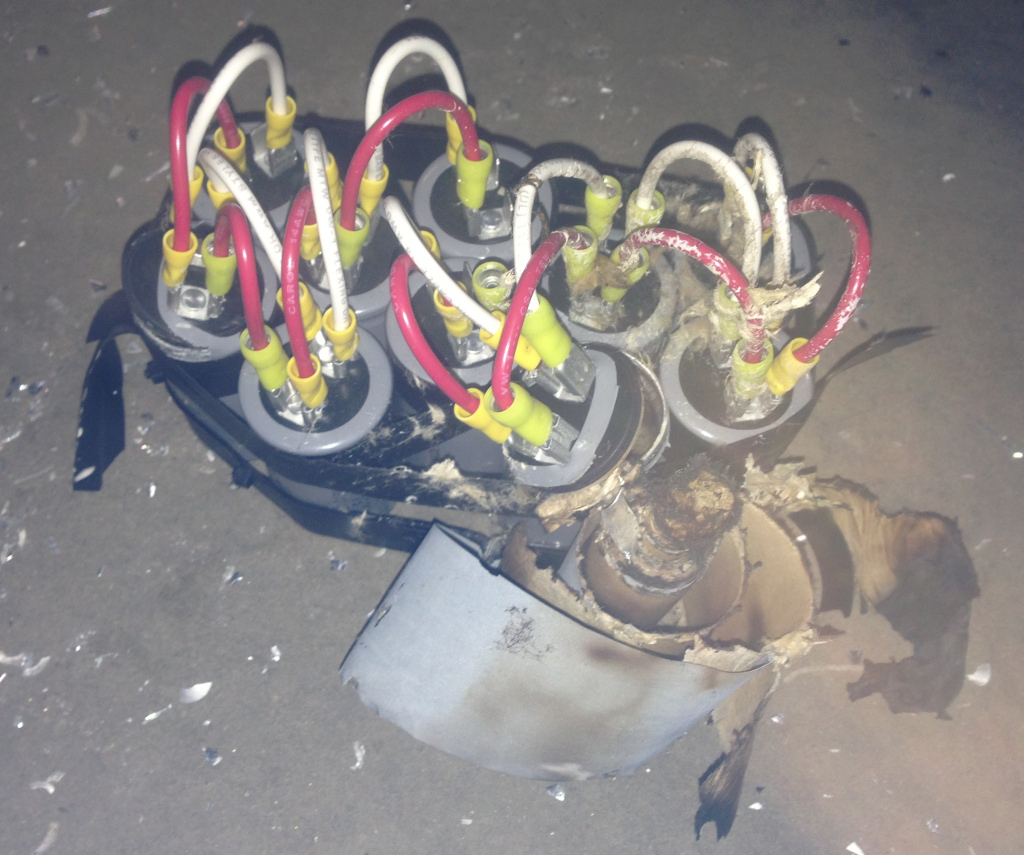
After throwing the mighty disconnect to ‘on’ once more, I pressed the just-tweaked red start button again, and the system fired up.  However, things were not sounding right, so I pressed the black stop button right away.  I surmised that the growling must be due to loose items sitting atop the plywood sheet that adorns the RPC cart (and acts as more horizontal storage space than I care to admit).  So I pressed the red start button again, and let the system growl angrily while I prepared to turn some perfectly good aluminum tubing into swarf.  After perhaps 10 seconds, there were loud popping sounds coming from the RPC, followed by me hopping around trying to turn off every electron flow nearby.  After I finally hit the main disconnect, I had a look at the carnage underneath the plywood sheet, where we both saw some rather impressive green flames emanating from what had been the bank of starter capacitors.

“Um, what temperature do electrons burn at?” he quizzed, a highly amused grin on his face.  After I had finished blowing out the flames (note to self – buy fire extinguisher for garage) and giggling over the absurdity of the situation, I determined that finishing the scope rings would simply have to wait for another night.  We pulled out the smoking remains of the capacitor bank and had a look.

So, that’s what’s inside an electrolytic capacitor – foil, paper, and magic smoke.  As everyone knows, once you let out the magic smoke, nothing works correctly, and you can’t get the smoke back into the component it escaped from.  After I checked my notes (that is, my previous blog posts on actually building the RPC), I re-familiarized myself with the circuit.  I had connected the starter capacitors directly through another pushbutton module, as I didn’t have a suitable relay at the time.  I recalled consulting with our EE at work about the use of just the pushbutton for the starter capacitor array, and he said that while it wasn’t ideal given the amperages in play, it would probably hold up just fine for several dozen to a hundred startups, which sounded just fine to me at the time (and then I promptly forgot about that limited lifespan).  I don’t know exactly how many RPC startups I’ve had since building it, but it’s certainly within that range – he gets major bonus points for accurate estimation of the failure mode and timeframe.

Really, I should have noted the signs of excessive current when I first pulled the pushbutton out of the panel.

The melted plastic housing right next to the screw terminal at the very rear of the module is a dead giveaway for “something ain’t right over here”.  So I replaced that module with a spare that I had, and decided to actually do things correctly this time.  Well, more correct at any rate – if it blows up again, I may have to reconsider my approach.

I used an Allen-Bradley contactor (the gray device on the left) with the 120v coil wired in to the start switch by way of the step-down auto-transformer (black box in the upper right).  The previous bank of ten 64mfd start capacitors (bits of their innards still sprinkle various components) has been replaced with three 208mfd caps (which I would have used initially if Surplus Center had them in stock at the time).  The big rectangular run capacitors remain unused, the poor things (well, it’s a better life than erupting into a cloud of electrolyte and flame).

Starting the newly repaired RPC was not quite as nail-biting an experience as the very first time, but still caused me to grit my teeth when pressing the red button.  Fortunately, all my work had been properly done, and the RPC started up in a flash without issue.  In fact, it seems to be even more reliable at this point – I’ve started it up perhaps 5 times or so, and each time was perfect.  I didn’t have to release the start button after 1.2 seconds because it didn’t sound quite right – every start has been confidently powered, with no hesitation.  The scope rings were turned with ease, and the system is better than ever!

Gunsmithing with a 3D printer – Part 4

Well, to say that a lot has happened since Part 3 would be something of an understatement.  To recap: Defense Distributed tried printing my AR lower STL on an Objet machine, but it only held up for 6 shots.  While much was made in the media about this ‘failure’, I thought it was actually an […]

Well, to say that a lot has happened since Part 3 would be something of an understatement.  To recap:

Defense Distributed tried printing my AR lower STL on an Objet machine, but it only held up for 6 shots.  While much was made in the media about this ‘failure’, I thought it was actually an excellent demonstration of material properties in the two different 3D printing technologies used.  My FDM printed lower used material with a higher impact strength, while the Objet printed lower was stiffer.  As a result, mine flexed and would not cycle properly with .223 ammunition, while Defense Distributed’s lower cycled perfectly with 5.7x28mm ammunition, but fractured at the root of a buffer tube thread (interesting how the extreme detail afforded by the Objet process actually created stress risers due to the threads in my STL model being perfect ‘V’ profiles with no filleting of the thread roots).  They’ve since refined the model to hold up for 600+ rounds, which is quite impressive for a photopolymer.

Representative Steve Israel started calling for renewal of the Undetectable Firearms Act, and has also called for making 3D printed firearms and homebuilt ‘undetectable’ polymer magazines illegal.  I’m taking this somewhat personally, as he keeps using a giant photo of my AR lower as .22 pistol during his press conferences – the least he could do is put my URL on the photo to provide proper attribution.  Given that some of the most popular rifle magazines commercially made today are of polymer construction, I’m not sure what he’s really hoping to accomplish by expanding a law that was passed due to media hysteria over the introduction of the ‘plastic’ Glock pistol.  Wait, media hysteria over plastic guns?  The more things change, the more they stay the same…

After the horrific shooting in Connecticut, Thingiverse pulled almost all of the firearm related files, including my AR lower and a Magpul style trigger guard I had designed.  I immediately contacted their legal counsel and pointed out that a trigger guard is a rather important safety device and has use in paintball and airsoft, not just firearms.  The response was ‘our sandbox, our rules, and we can change the rules at any time’ (but spoken in far more lawyerly terms).  An AR-15 grip that had also been taken down was reinstated a few days later, so I’ve been asking how to get my trigger guard reinstated as well.  However, my requests appear to be ignored, and I’m somewhat giving up on Thingiverse at this point.  It’s still a great community, but when I can’t use it to share with other gunsmithing hobbyists or even paintball and airsoft enthusiasts, my desire to use it naturally diminishes.  Meanwhile, Thingiverse appears to have no issues with people sharing drug paraphernalia designs, so maybe they’re attempting to cater to a rather different group of ‘hobbyists’.

For anyone interested, I have a copy of my original AR lower STL here (though I don’t really recommend it at this point – there are much better 3D printable lowers that have been designed and refined by other folks).  I have a copy of the trigger guard here.  It comes in two versions – one is the standard version that uses a roll pin through the rear holes, and the other I designed to be a tool-free version that uses angled studs to snap into place.  I’m actually rather proud of this version, and would be happy to hear feedback on it.

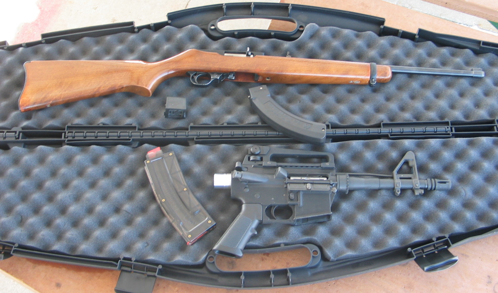
Back to the present – I really haven’t done anything further with the printed AR lower, as I’ve been experimenting with a different firearm platform.  Commenter Allen had asked “Could the Ruger 10/22 receiver be built the same way?”  This certainly got me wondering, as the 10/22 receiver, unlike an AR-15 lower receiver, is what the barrel attaches to, and contains the reciprocating bolt.  Additionally, the fire control group (trigger, hammer, etc.) is contained in a modular pack rather than having those components fitted individually to the receiver.  Plus, answering this question seemed like an excellent excuse to finally purchase a 10/22 – like the AR-15, it’s an incredibly popular rifle with countless aftermarket accessories available.  Additionally, it’s a great platform to learn the fundamentals of proper marksmanship (one of the many skills that I’d like to learn one of these days).

I found a very well used one at Gander Mountain for a reasonable price – the sling swivels had apparently broken off long ago and the receiver finish was a bit worn, but it looked to be in good functional order and would do well for learning how the rifle operates and is constructed.  When I got it home, I eagerly dug into the disassembly to see how it functioned and to give it a much needed cleaning.  The 10/22 is a semiautomatic, blowback operated .22 rifle.  The blowback operation means that unlike the AR-15, the bolt is not locked into place when the gun is fired and is only kept forward by means of the recoil spring.  A blowback bolt is also quite heavy in comparison to the cartridge used – this is to ensure that the bolt begins its rearward travel in the firing cycle slowly enough to let the chamber pressure decrease to a safe level before the spent cartridge is extracted.  The receiver itself is cast, though there are aftermarket billet receivers available for those looking to heavily customize the rifle.  In looking at how the bolt reciprocates in the receiver, it appeared that there should be no issues with a 3D printed receiver, provided that the print is made so that the layers are parallel to the barrel axis (to provide as smooth a surface as possible for the bolt’s travel).

For the printed receiver itself, I again turned to Justin Halford’s cncguns.com for an IGES file.  Unlike the AR-15 lower receiver, there weren’t any design features that I felt needed strengthening right away, so I created an STL file directly from the solid model and set it running with the same Bolson black ABS I had used for the AR lower.  I printed the receiver upside down so that the interior didn’t need any support material, and thus would provide as good a finish as possible.

After removing all evidence of support material, it was time to start fitting parts.  Chief among these is the barrel itself, but the hole in the receiver was slightly undersized (not unexpected, and better than being oversized).  I clamped it to the angle plate on the mill and indicated it in vertically with a dial indicator and coaxially with a Blake co-ax indicator before opening up the hole with the boring head.

After bringing the hole to appropriate size (I could just begin to insert the barrel shank), I tapped the barrel clamp holes with 12-24 threads (thanks to the blueprints at fireamfiles.com) as well as the stock mounting screw hole in the front tang.

Next was to actually test installation of the barrel itself, which tightened up nicely, but I noticed that the barrel would visibly cant downward as I tightened the clamp screws.

After removing the barrel, I saw that there wasn’t quite enough clearance on the front counterbore, and the back of the barrel was catching on the top front edge of the receiver.  So it was back to the boring head to enlarge the diameter on the mating face slightly.

Then, it was time for a test fit of the bolt – it was a tight squeeze to get it past the rail on the inside right of the receiver.

As it turned out, I think the rear wall of the receiver in the original IGES file may be a touch too thick, as I also couldn’t get the trigger pack installed, so I thinned out the rear by perhaps 0.030″ until I could just get the retainer pins to go through the receiver and trigger pack (I had already reamed out the holes in the receiver at this point).

With that done, I could finally fit all the internals and actually dry fire the gun.

However, when I tried to drop the receiver assembly into the wood stock, it wouldn’t fully seat.  After fumbling with it for a few minutes, I noticed that there is an extra relief cut on the original receiver at the interface between the tang and the receiver front.  As it turned out, the original IGES file does indeed have this relief cut, but when I brought it into SolidWorks, I had run a feature recognition pass on the part.  For some reason, SolidWorks removed this feature – I should have just done a direct export to an STL file instead!  Oh well, one last machining pass on the mill took care of it.

The barreled action fit just fine in the stock, and both the 10 and 25 round Ruger magazines fit, though perhaps a little more loosely than desired.

Today I took it to the range and found an accomplice to act as a model.  Naturally, I let him burn through some rounds on the 3D printed AR receiver configured as .22 pistol first.  A .22 AR pistol is kind of a ridiculous contraption, but it is also ridiculously fun.

Next was the test of the printed 10/22 receiver.  As with previous testing, I started with only 1 round in the magazine and worked my way up.  Things were running just fine, so I put in the 25 round magazine and let ‘Secret Agent Man’ have some trigger time with it.

Generally, it ran nicely, though we did have some feed issues with it.  I think the fitment of the magazine could be to blame, as it seems that the front of the magazine is able to tip down a little too far.  Both magazines are also absolutely brand new (this was their first usage), and I’ve been told that 10/22 magazines operate better after an initial break-in period.

So there you have it – a 3D printed 10/22 receiver is entirely feasible!