Stratasys EEPROM hack revisted

Five years ago, I published what is probably the single most popular post on this blog – namely, how to reset a Stratasys material cartridge EEPROM so that it can be refilled with much cheaper third party filament.  Dan at gnurds.com took things a step further and came up with some great step-by-step tutorials on […]

Five years ago, I published what is probably the single most popular post on this blog – namely, how to reset a Stratasys material cartridge EEPROM so that it can be refilled with much cheaper third party filament.  Dan at gnurds.com took things a step further and came up with some great step-by-step tutorials on how to accomplish this, and even had a post featured in hackaday.  I received a lot of questions and feedback on the hack (and even helped hack a few machines running in the field), but the fact that the process requires modifying contents on the printer’s hard drive put it out of reach for users who were barred from doing any sort of ‘invasive surgery’ on the machine (generally students stymied by school officials).  What was needed was a truly ‘touchless’ hack that didn’t require any modification of the base machine itself – we needed a way to actually generate our own EEPROM data from scratch rather than simply re-using the EEPROM data as it had come on the cartridge from the factory.  The problem is that the EEPROM data is encrypted.  Worse, my understanding of how DES crypto is done on a practical level is pretty much zero – I’ve done embedded programming before, but this sort of stuff is far outside my area of expertise.

Fortunately, in 2013 a wizard cracked the EEPROM crypto and posted the code to github!  Benjamin’s sorcery is just what’s needed to build your own EEPROM image, and he’s put a great deal of time and effort into it for zero financial gain.  As a result, it really bugs me when I see people using his code to sell programmers for hundreds of dollars, with zero attribution for his work.  This post, then, shows start-to-finish how you can refill your own P-class Stratasys cartridge using only a Raspberry Pi.  It’s admittedly long and detailed, but I think it’s important to understand the whole process before trying to use any shortcuts.

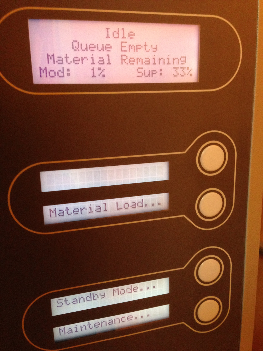
The reason that it’s taken me so long to document this hack is that I previously had no real access to a P-class machine.  Fortunately, my friends at Into3D LLC have one in their shop and were more than willing to let me attempt refilling one of their empty cartridges.  It’s a Dimension BST 768, which fortunately is still supported for 2 more years.  This is what the front panel looks like with a near empty (1% material remaining) model cartridge:

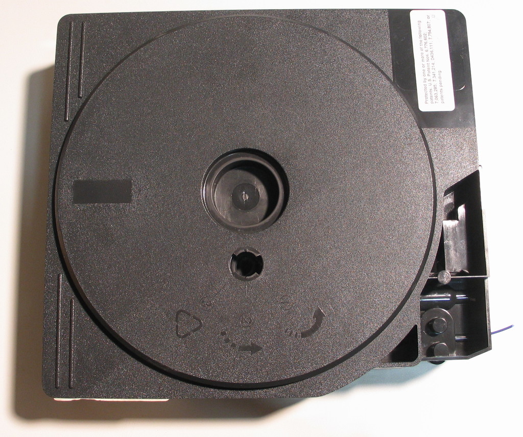
Here’s that very cartridge – the label on top lists some applicable patents (6776602, 7063285, 7341214, D436111, and 7754807):

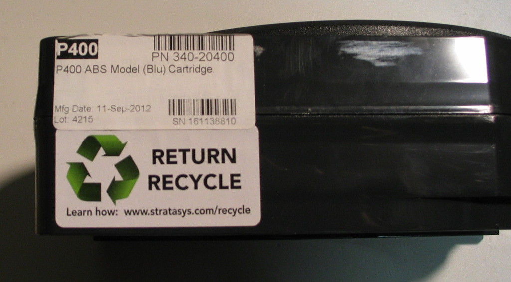
The side has a recycling information label and identifying information for the cartridge itself – we’ll see how that matches up with the information on the EEPROM itself.

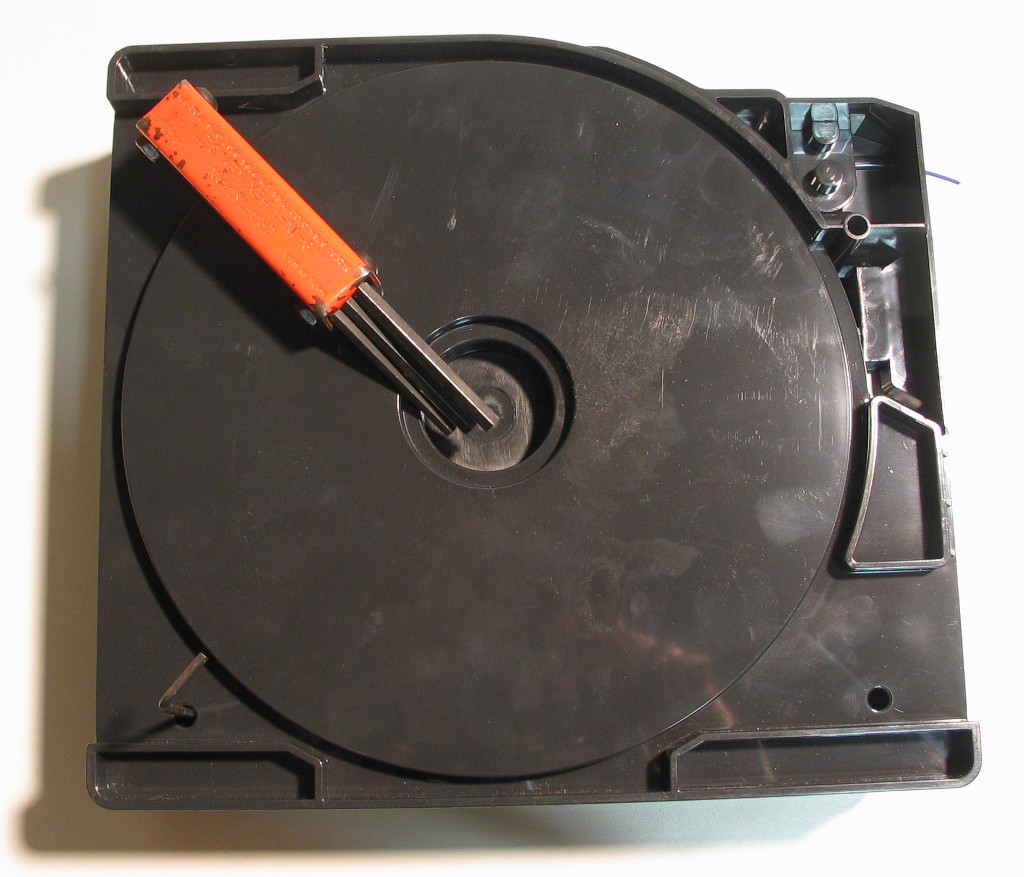
Use a 7/32″ hex wrench to remove the 4 screws on the underside of the cartridge (I used a fold-up set to break them free first, then a standard L-wrench to remove them).

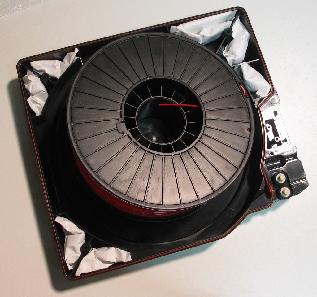
Then, flip the cartridge over and give the shell a few raps with your knuckles to shift the internal desiccant packs into the bottom half.  Carefully lift off the top half of the cartridge, exposing the 1% of material remaining on the spool:

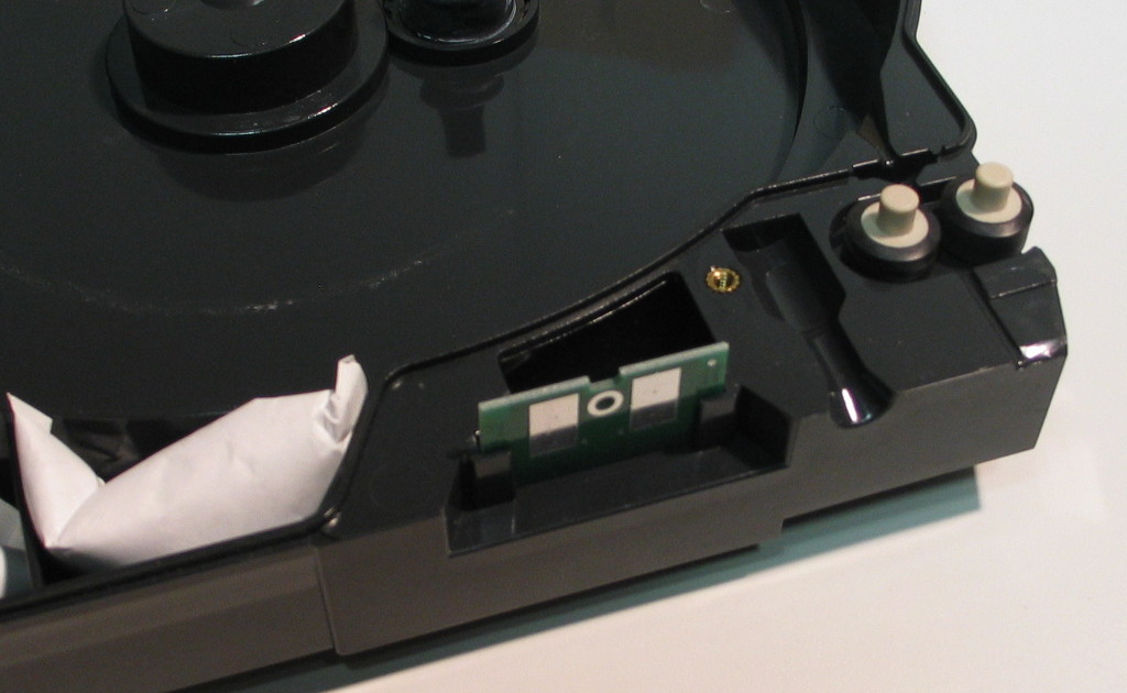
Despite my dislike of using cartridges for 3D printers (it’s a lot of excess material to house the consumable), these are actually quite well designed – there’s a pair of very simple drive wheels at the corner exit, and the other 3 corners get desiccant packs.  The orange-brown circumferential seal has a spot for the filament to exit through, and the screws actually thread into brass inserts, not into the raw plastic.  A single cartridge can be reused many times, potentially lasting a fair portion of the life of the actual machine.  Parked right next to the drive wheels in a slot is the object of our interest, the EEPROM board itself:

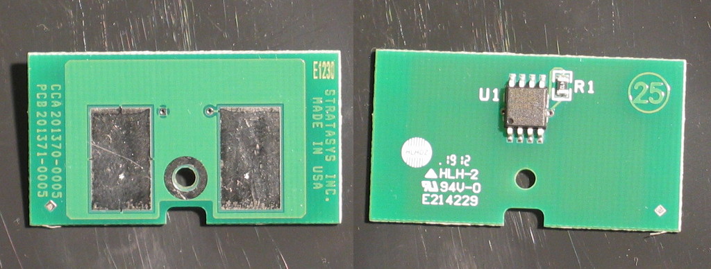
Here’s what the front and back of the EEPROM PCB looks like:

In case anyone is wondering, the text on the chip itself is:

DS2433
1226B1
586AC

As noted in the original blog post, the chip is a DS2433 (originally a Dallas Semiconductor product, hence the ‘DS’, now owned by Maxim).  Importantly, it is a 1-wire device, hence requiring only 2 contacts to the chip.  As an aside, this nomenclature has always annoyed me – power and signal may be carried over a single wire, but you still need a ground connection.

Now, to extract those pesky bits from the EEPROM, all 4096 of them!  Technically, there’s a few more bits that we’ll need as well – a 48-bit serial number, 8 bits for CRC, and an 8-bit family code (0x23).  I’ve used a Bus Pirate before, and you can use an Arduino as well, but for this post I’ll be showing how to use a Raspberry Pi, since we can do everything on a single, standardized platform.  In this case, I’m using a Raspberry Pi model B with an Adafruit breakout board, and I started with a clean NOOBS image (v1.7.0 to be specific) on a freshly formatted SD card.

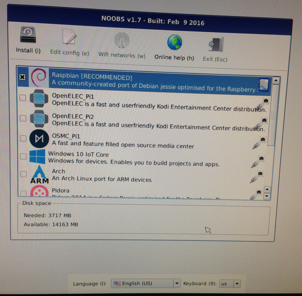
I booted the RasPi and was greeted with the installer – since I had the RasPi connected to my network, it provided me with network installation options, but I selected only the first option to install the Raspbian OS:

While that was installing, I prepped the breakout board.

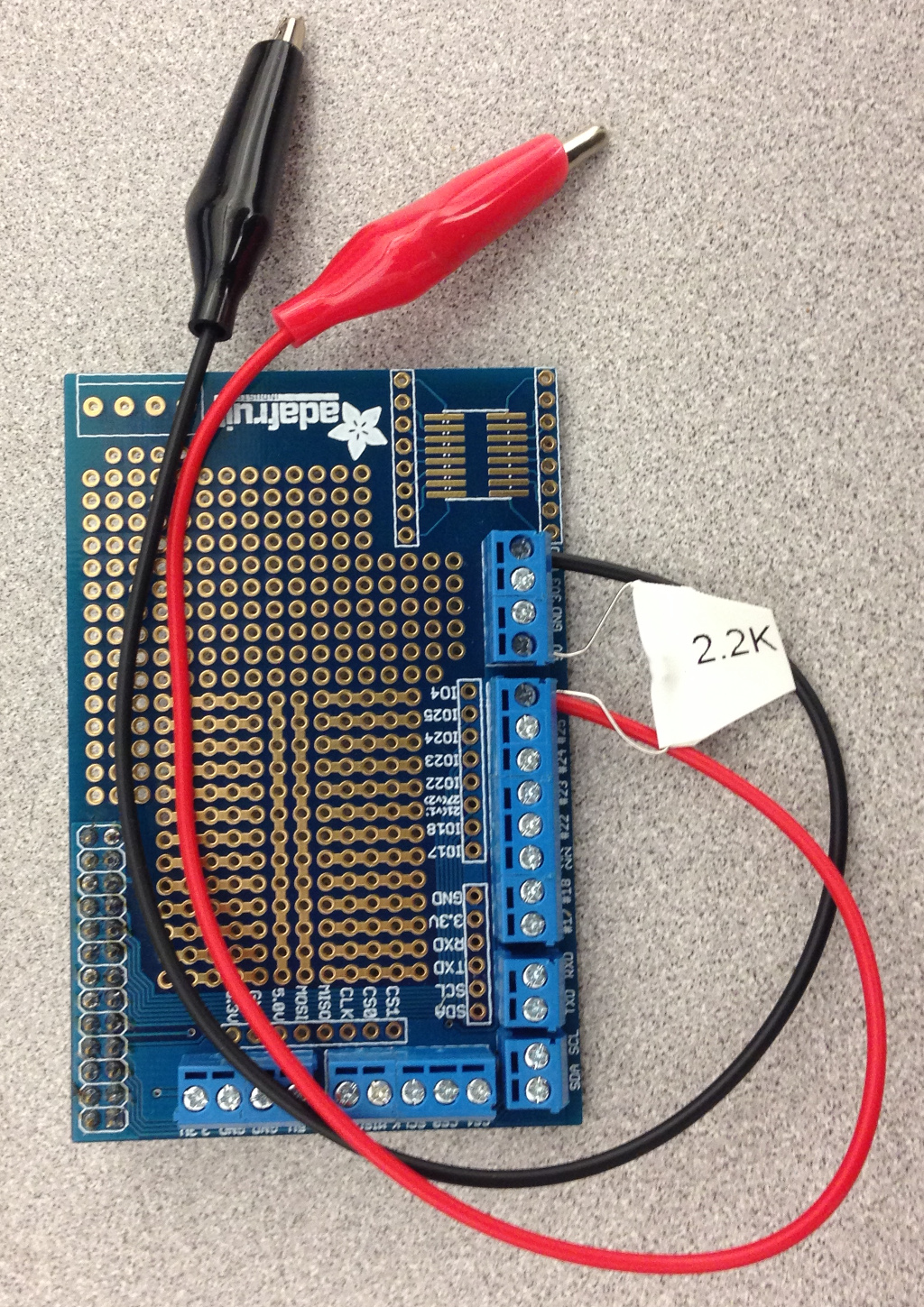
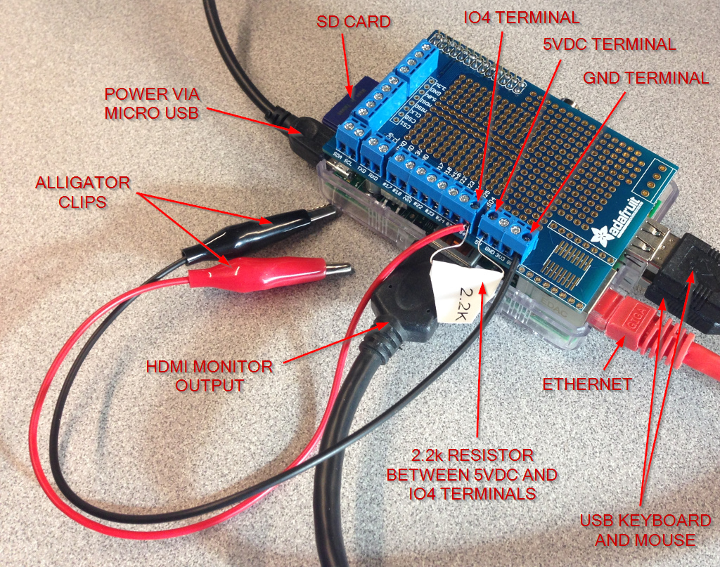
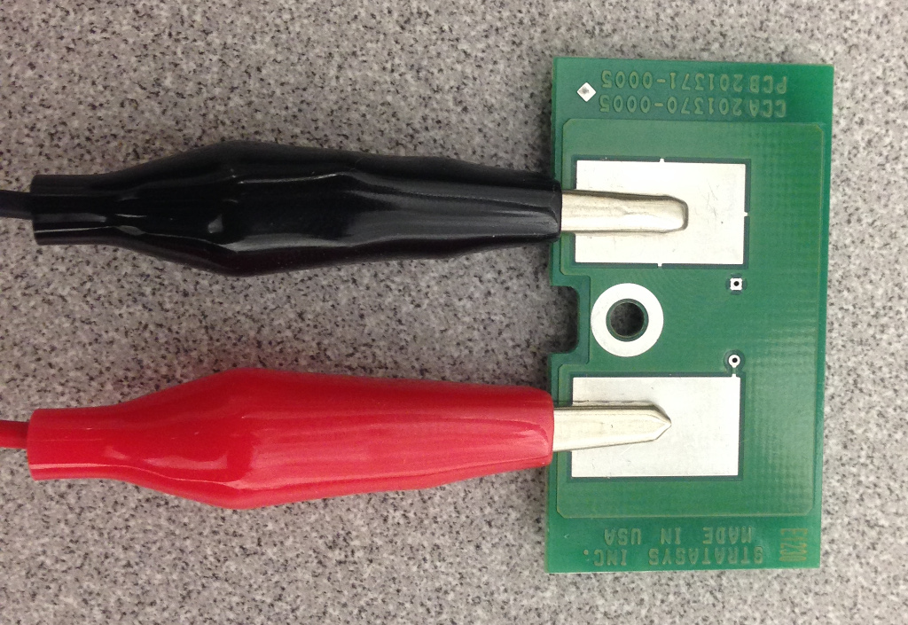
I connected the black alligator clip to a GND (0vdc) terminal and the red alligator clip to IO4 on the breakout board (which is pin 7 of the RasPi header).  Note that pinouts on the RasPi can be very confusing – IO4 on the breakout board is not GPIO.4 on the RasPi as I had first thought, but pin 4 of the Broadcom BCM2835 processor at the heart of of the RasPi (also known as GPIO.7 on the RasPi).  You can read more about this confusion at wiringpi.com.  I connected a 2.2k resistor to a 5vdc terminal and the IO4 terminal – this acts as a pullup.

By this time, Raspbian had finished installing and I was looking at a fresh new desktop.  I find it easier to just SSH into the RasPi, so once I determined its IP address (just hover your mouse over the network icon in the upper right of the desktop), I could fire up PuTTY and connect right to a shell (you can certainly do everything via a terminal window on the desktop, though).

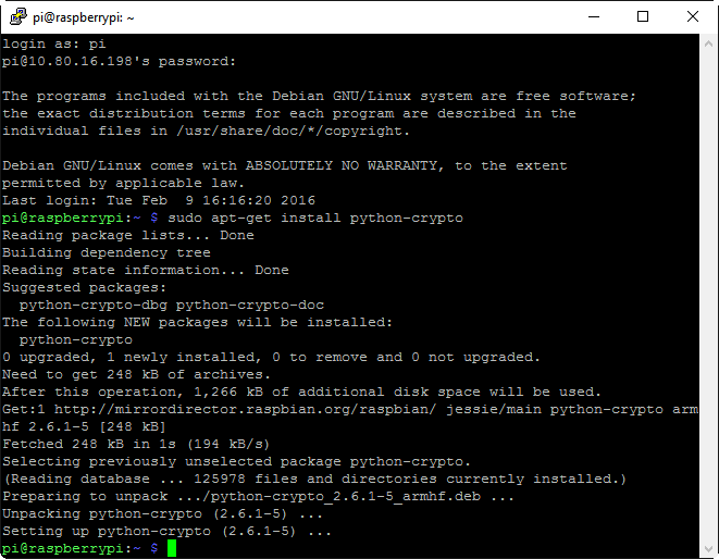
On a default install of Raspbian, the login is pi and the password is raspberry.  While Raspbian includes just about all the software we’ll need by default, the Python crypto library will be required later on, so run sudo apt-get install python-crypto right away to install that package (the RasPi will need to be network connected with internet access for this to work).  I then attached the breakout board to the RasPi and proceeded to do some testing with gpio to make sure that my wiring was correct.

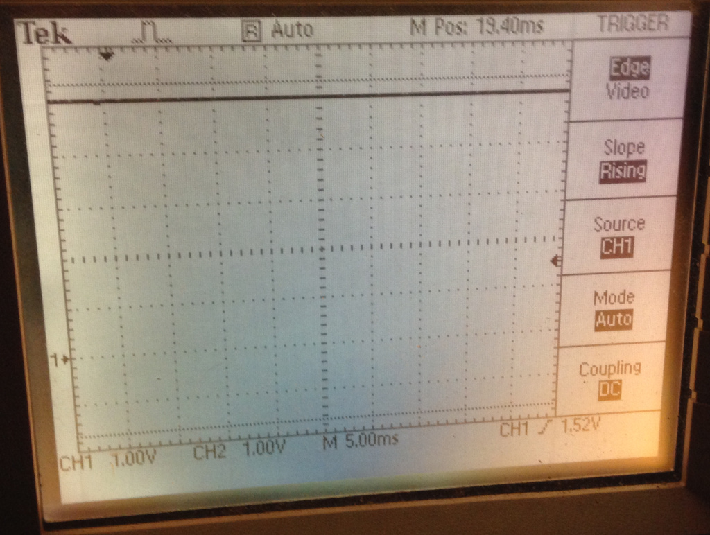
I hooked up an oscilloscope to the red and black leads (you can use a multimeter, but a scope will let us see when EEPROM reads are occurring, which is handy when debugging), and saw that I had nearly 5vdc, which is just what I was expecting due to the 2.2k pullup resistor.

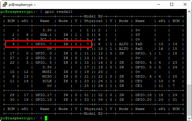
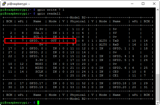
Now, let’s have a look at actually controlling the pin that the red alligator clip is connected to.  The gpio readall command gives us a snapshot of what the status is of all the header pins (again, see wiringpi.com for details).  By default, all the I/O pins are set to be inputs (note pin 7 is set as ‘IN’):

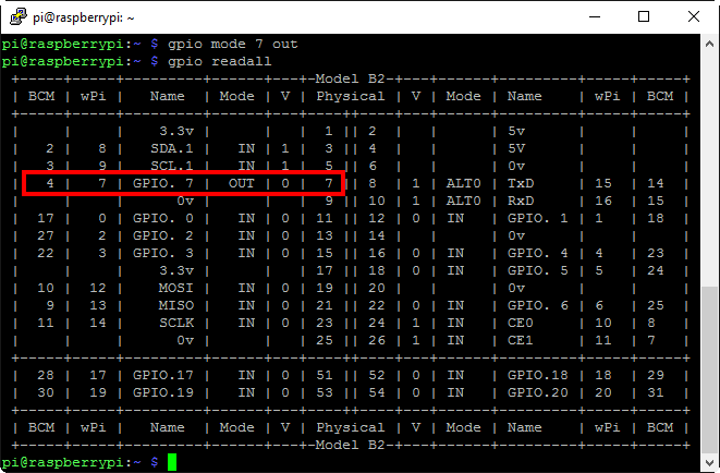
We can change the mode from input to output on that pin with gpio mode 7 out

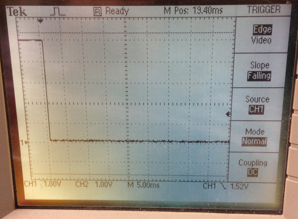
And as soon as that command is issued, the voltage drops to zero:

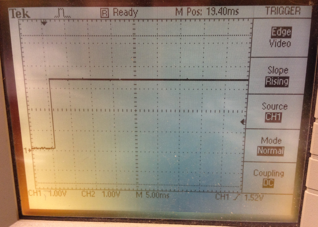
Issuing gpio write 7 1 will bring that pin high:

Resulting in 3.3v output (RasPi digital I/O is 3.3v, not 5v):

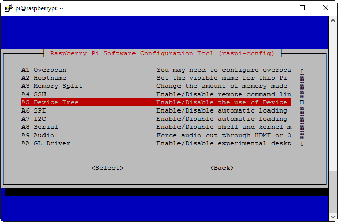
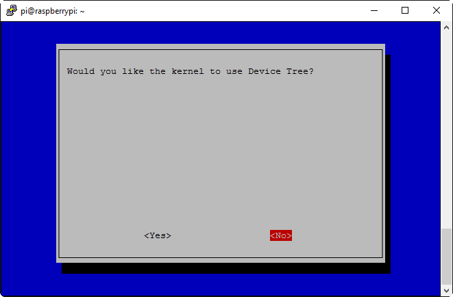
That’s all for verifying that the wiring is correct.  There’s one final change to make before we can actually try reading in an EEPROM, and that’s disabling Device Tree (I understand it’s possible to get things working with DT enabled by means of some other configuration changes, but disabling it altogether is the route I went with).  Run sudo raspi-config to bring up the configuration menu, and select Advanced Options:

Then, select Device Tree:

Select ‘No’:

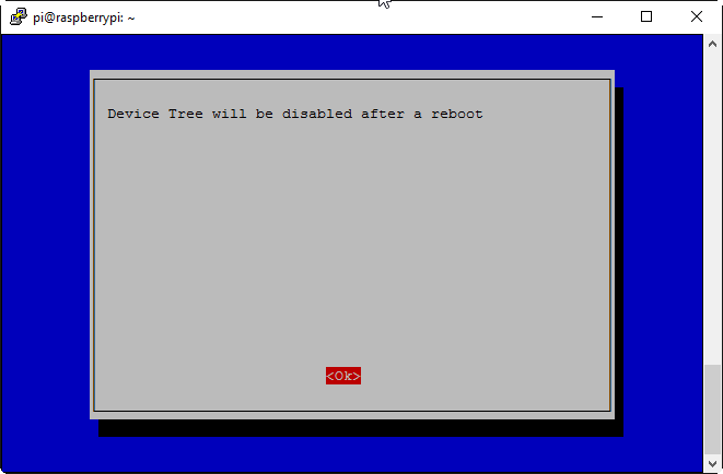
And DT will then be set as disabled:

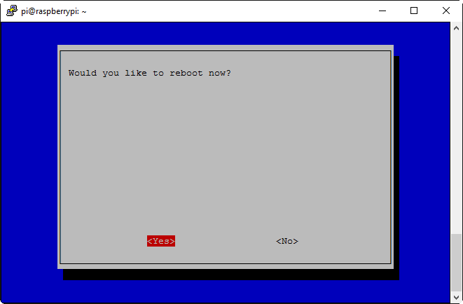
Back at the main menu, select Finish and you’ll be prompted to reboot (select ‘Yes’):

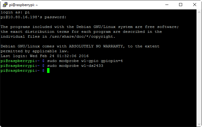
With the RasPi rebooted, we’re finally ready to read in an EEPROM.  Recite the magic incantations sudo modprobe w1-gpio gpiopin=4 and sudo modprobe w1-ds2433 (note that you’ll need to run those commands again if you reboot the RasPi, so it may be worthwhile to add them to a startup script):

Now, connect the clips to the EEPROM – black clip to the ground pad, red clip to the data pad (you can tell which is the ground pad because it has a trace on all 4 sides connecting it to the ground plane):

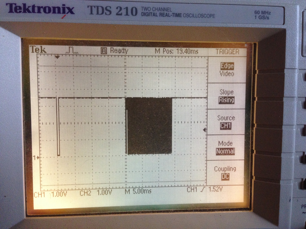
If you have a scope hooked up, you’ll see that the voltage drops to 3.3 volts and then there will be a data read every 10 seconds or so:

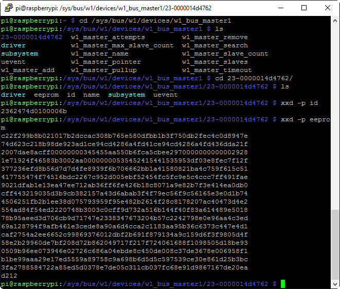
We can cd /sys/bus/w1/devices/w1_busmaster1 to have a look at the connected 1-wire devices seen by the RasPi, and therein is a specific directory created for that EEPROM (23-0000014d4762 in this case – your EEPROM will be different!):

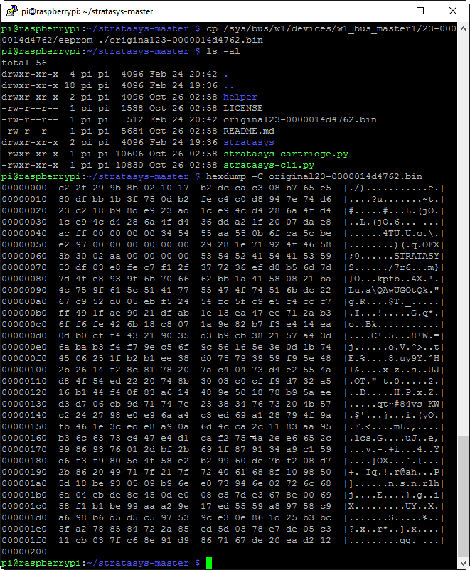
You can also use the xxd command to hex dump the EEPROM’s full UID as shown (0x2362474d0100006b).  This particular UID consists of the family code (0x23, which should be the same on all Stratasys P-class EEPROMs, except for those used on uPrint cartridges), the device serial number (0x62474d010000 – note the endianness) and finally the checksum (0x6b).  The screenshot also shows a dump of the 512 bytes of EEPROM data itself.  In order to actually do anything with this EEPROM data, though, we’ll need Benjamin’s code.

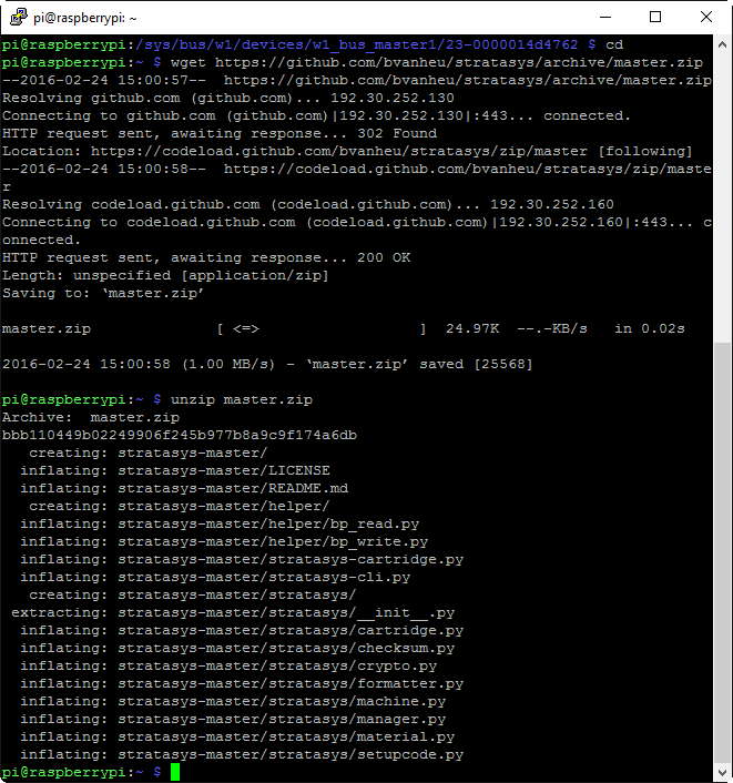
We’ll cd back to our user directory and then grab a .zip archive of the code via wget https://github.com/bvanheu/stratasys/archive/master.zip, after which we can extract it into a directory via unzip master.zip.

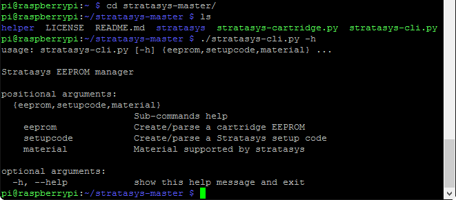
We’ll cd into that directory and try running the main program by executing ./stratasys-cli.py -h

This is just what we want to see!  If instead you get a number of errors mentioning crypto, make sure that you have the python-crypto library installed.  At this point, we don’t need to do any further configuration on the RasPi, and we can actually dive into the EEPROM data itself.  If you’ve managed to get this far, you’re probably capable of basic command line Linux work, so I’m going to gloss over those details from this point onward and let screenshots do most of the talking.  First, we’ll copy the EEPROM data out to a file that we can actually work with.

A directory listing confirmed that the resulting file is exactly 512 bytes in length, and all the formatting looks just like all the other Stratasys EEPROM dumps I’ve seen.  Let’s take one more look at the EEPROM UID, as we’ll need to format it correctly to feed into the stratasys-cli program:

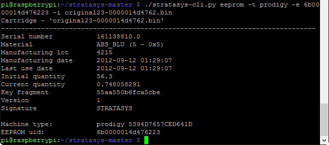
We need to reverse the byte order of the shown UID, so instead of 23 62 47 4d 01 00 00 6b we’ll use 6b 00 00 01 4d 47 62 23 (remember, the family code of 0x23 is at one end, and the checksum is at the other end).  Here we finally feed the EEPROM UID and the EEPROM data through the program, using ‘prodigy’ as the machine type (any Dimension series machine should be ‘prodigy’, but a different machine type (Titan, Maxum, etc.) will have a different family name):

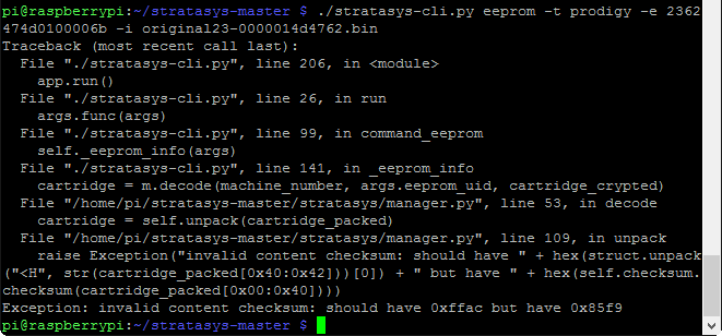
If you don’t have the UID formatted properly, the program will fail with a checksum error:

If we take a quick look at the data, everything agrees with the label that was on the cartridge – the color, serial number, manufacturing lot, and manufacturing date all match perfectly (I’m guessing that the timestamp on the EEPROM data is actually GMT).  Note that while the last use date is a separate entry in the EEPROM data, I’ve never seen it differ from the manufacturing date (maybe Stratasys intended to write this data back to the cartridge, but couldn’t be certain that the printer itself would actually have the correct day/time set).  A service manual I saw indicated that this timestamp was intended to be the date/time that the cartridge was actually first inserted into a machine, so perhaps Stratasys intended to have cartridges ‘expire’ after a certain amount of time.

The EEPROM stores material quantity in terms of cubic inches.  A brand new cartridge contains 56.3 cubic inches worth of filament, and the current level as shown on the EEPROM is under 0.75 cubic inches, so the 1% filament remaining message on the printer’s front panel was right on (there was actually a little more than that remaining on the reel, but the overage allows for nozzle purges, waste due to swapping cartridges, etc.).  The original hack worked by simply setting the current material quantity back to 56.3, but the printer would remember the serial number of the cartridge (and refuse to work with that cartridge serial again), so files needed to be deleted on the printer itself.  Since we can now create our own EEPROM images from scratch, we can simply change the serial number in addition to the material quantity, and the printer will be none the wiser.

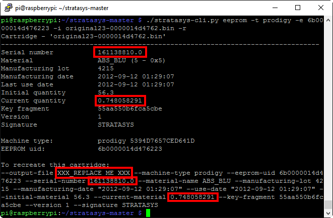
In addition to decrypting the EEPROM data and displaying it in a human readable format, Benjamin’s program can provide all the parameters needed to generate that very EEPROM data, which is extremely handy.  We’ll simply tack on the -r option to the command we just used:

We only need to change the highlighted options to create our desired EEPROM image:

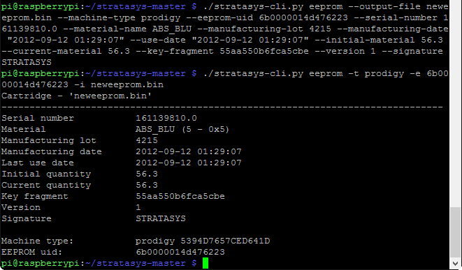
Reading the generated neweeprom.bin file back through the program shows that the serial number is now different (I incremented the value by 1000 rather than 1 just in case there were consecutively serialized cartridges the machine had already seen), and the material quantity is back to ‘full’.  Now, we can finally write that file back to the EEPROM itself (remember to use sudo when writing to the EEPROM due to permissions):

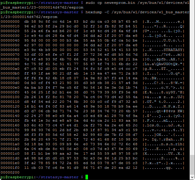
A quick hexdump directly from the EEPROM verifies that we’ve modified the contents successfully.  Note that the new image we generated is only 113 bytes, while the original EEPROM data is a full 512 bytes.  This is because everything after the ‘STRATASYS’ at 0x69 is random garbage (early on, Stratasys simply padded out 0x71 onwards with zeros), so that portion of the EEPROM can be left unchanged.  That’s all that we need to do with the RasPi – the EEPROM can be disconnected and set aside.  All that remains is to reload the cartridge with fresh material.

My favorite current filament is the ‘High Performance ABS’ from Coex3D – I’m partial to them because they’re local, their product quality is excellent, and Chris gave an amazing presentation on polymer processing and filament extrusion to our 3D printing user group a few years ago.  He listened to my pleas for MG94 filament and thankfully started producing it.

While Coex3D reels fit right into my FDM series machines, they don’t fit into P-class cartridges (the bore is just a little too small, and there is a rubber piece attached to the top shell of the cartridge that would interfere anyhow).  So I needed to respool the new filament onto the old reel.

In fact, respooling the filament itself is probably the hardest part of the entire process!  I admittedly got a bit hackish with the use of electrical tape as a makeshift drive dog, but it worked.

Make sure that you have the desiccant packets in place, the EEPROM PCB in its slot, and the drive wheels in position, then very carefully feed the end of the filament through the hole in the disc portion of the gasket.  Hold the filament in its guide slot, and carefully place the top shell half back in place (this is pretty tricky without having the gasket jump out of place).  Flip it over, assemble the cartridge with the 4 screws, and our work is complete.  Now, for the moment of truth…

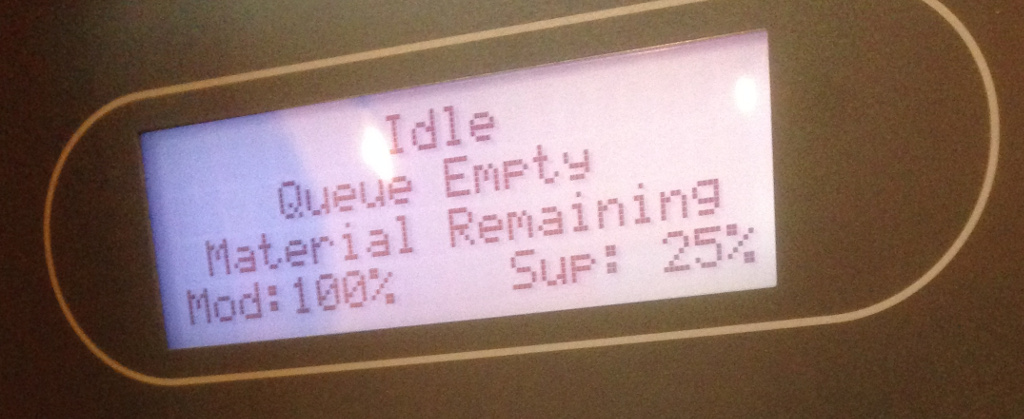
After loading the refilled cartridge into the printer, it showed a 100% full model spool!

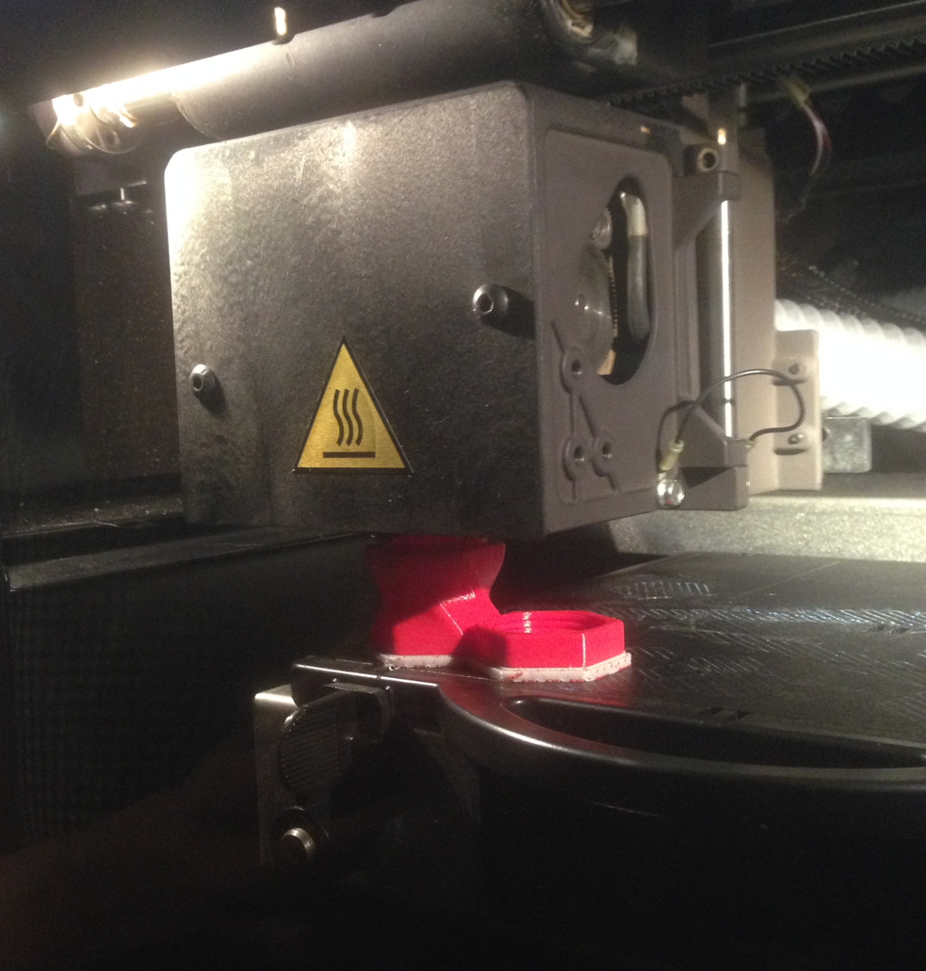
Of course, the proof is in the prints, and the machine is now happily churning out parts far more inexpensively than before (and with better material properties than the OEM P400 filament had).

Notes:

1) Benjamin’s code works for other Stratasys printer families as well, including the big T-class and Maxum/Quantum machines.  It will even decrypt and generate binary images for uPrint cartridge EEPROMs.  However, uPrint cartridges use a different EEPROM model that unfortunately utilizes an HMAC authentication scheme for writes.  So while you can read EEPROMs and generate new .bin files, actually writing them back to the EEPROM is impossible without knowledge of the secret key used for the HMAC authentication.  If you only have access to a uPrint, you’re kind of stuck. [12FEB2017 addendum]  It turns out that an HMAC protected EEPROM can be re-written by using the DIAG port on the printer.  ‘Odin’ discovered this workaround and authored these concise instructions for the hack.  This isn’t quite ‘touchless’, but until someone breaks or sidesteps the HMAC protection, it’s the best option.

2) 56.3 cubic inches isn’t actually the maximum material quantity you can set on the EEPROM.  It’s a floating point number, so the sky is the limit!  However, on a P-class machine, 60.0 cubic inches is the maximum that the printer will accept as valid, as anything larger will instead be considered zero. [22FEB2017 addendum] Reports indicate that larger volumes can be used, but the ‘initial material quantity’ field needs to be similarly large.  However, others (Odin, for one) find that this doesn’t work on their machine, so this could be a difference between firmware revisions.

3) I mentioned using an Arduino to read/write the EEPROM.  There’s actually a fork of Benjamin’s code available on github called CartridgeWriter that runs in Windows and interfaces with an Arduino for EEPROM reads/writes.  I haven’t tried it myself, but others have used it successfully.  I prefer running Benjamin’s code directly on a RasPi due to the amount of control it provides.  Specifically, it makes some automation possible, such as…

4) …this clever little EEPROM rewriter made by Sneaks Hacks.  He’s posted the wiring schematic and STL files for the housing, and is currently working on an updated version as well as documentation for people wanting to build their own.

5) The Stratasys EEPROM PCB has a surface mount 4.7k pulldown resistor right next to the DS2433.  While most wiring schematics for reading/writing a Stratasys EEPROM show to use a 4.7k pullup between 5v and the data pad, I used a 2.2k to help ensure that voltage to the DS2433 remains in an acceptable range.  You can certainly start with a 4.7k pullup and reduce the resistance if you’re having flaky results, but I don’t think I’d go below 2.2k.

6) Benjamin notes that use of the –output-file option when generating EEPROM images isn’t actually correct in a traditional Unix sense, and that I/O redirection is really the proper Unix way to get binary output from stratasys-cli.py (that is, using something like ./stratasys-cli.py –foo –bar > my_file.bin).  I think using –output-file is a little easier to see and understand what’s going on, but if you’re building an automated system like Sneaks Hacks did, using stdout can help streamline the processing chain.  For example, you could write directly to the EEPROM and save a backup of the image all in one go by using something like ./stratasys-cli.py –foo –bar | tee backup_image.bin /sys/bus/w1/devices/w1_bus_master1/23-0000014d4762/eeprom.

7) Everything in this post is simply the compilation and distillation of other people’s hard work – I simply wanted to bring it to a wider audience.  These are the folks who deserve all the credit:

  • Huge thanks goes to Mjolinor, who I believe was the first to pioneer using a RasPi as an all-in-one solution for rewriting Stratasys EEPROMs.
  • Thanks to the anonymous and unnamed people (you know who you are) who have assisted in developing and testing these techniques over the past few years and helped review this post before publishing.
  • Steve, Joe, and John at Into3D LLC for letting me use their Dimension BST 768 as the guinea pig for this project.
  • First, last, again, and finally, Benjamin Vanheuverzwijn.  This man is an absolute electronic wizard and none of this would have been possible without him.  Send him coffee.
Gunsmithing the RAS-12 – Part 1

It’s no secret that I have a penchant for oddball guns, be they paintball marker or firearm.  Seeing a design that’s off the beaten path is always enjoyable, be it for mechanical ingenuity or sheer impractical novelty (though usually a peculiar blend of both).  During a recent visit to my friendly local FFL (always good […]

It’s no secret that I have a penchant for oddball guns, be they paintball marker or firearm.  Seeing a design that’s off the beaten path is always enjoyable, be it for mechanical ingenuity or sheer impractical novelty (though usually a peculiar blend of both).  During a recent visit to my friendly local FFL (always good for a rousing discussion and perhaps lightening of my wallet) a friend and I perused a distributor’s sale flyer and immediately spotted an intriguing item – a 12ga shotgun upper for AR-10 lowers.

For those unfamiliar with the AR-10, it is the bigger, older brother to the AR-15 rifle.  In fact, much of what was considered new or novel at the time of the AR-15’s introduction is properly credited to the earlier AR-10 design.  Unfortunately, there is far less standardization on the AR-10 platform than there is on the AR-15.  Eugene Stoner actually updated his AR-10 design decades later to have much greater commonality with AR-15 parts (resulting in the KAC SR-25), while Armalite (not the original Armalite that actually developed the AR-10, just somebody who bought the name and rights) developed the AR-10B using an upper from an SR-25, and somehow DPMS came up with a mashup of these designs, and then…  …yeah, I don’t really understand it all either.  We’re left with saying ‘AR-10’ as a generic terminology for something that looks like an AR-15 but fires a .308 round – as someone once wryly observed, “there’s an XKCD for everything“.
The important part is that the modularity of the AR-15 and AR-10 allows different upper receivers to be mounted to a common lower receiver (which is, as I’ve noted in previous posts, the one part that is itself considered the ‘firearm’ under US law).  While the AR-15 is far more standardized than the various AR-10 incarnations, the magazine well of the AR-15 limits what ammunition can easily be fed through it.  In fact, this limitation has been the underlying factor in the development of various new cartridges such as the .50 Beowulf, 6.8 SPC, .458 SOCOM, etc.  Although a 12ga shotshell by itself will just barely slip through the magwell of an AR-15 lower receiver, designing a practical magazine to feed that ammunition through said magwell is out of the question.  So, the next best thing is to scale up to the larger AR-10 lower receiver.

The ever-popular Magpul .308 magazines will happily accept a standard 12 gauge shotgun shell (extracting said shell is another matter, though).  The rimmed base of the venerable shotshell does not lend itself well to use in a box style magazine (as opposed to the tubular magazine that most traditional shotguns use).  As an aside, this issue isn’t unique to shotshells.  The rimmed base of the famous .44 Magnum round (feel free to insert your favorite Dirty Harry quote here) has limited its use in semiautomatic handguns to only 2 models in history, as far as I am aware – the iconic Desert Eagle, and Emilio Ghisoni’s masterpiece, the Model 6 Unica.

The designers of Kalashnikov derived shotguns (such as the Saiga-12 and Vepr-12) use special magazines with a fairly severe feed angle to improve reliability when stripping and chambering a round.  Unfortunately, that doesn’t translate terribly well to using a straight magwell and magazines designed for rimless ammunition.  The designers of the RAS-12 opted for a pretty radical approach to this problem – they designed their own ammunition.  Which is probably why I managed to snag this very interesting upper for less than a sixth of its original retail price – not much more than 2 years after announcing the product, the company doesn’t seem to be in business anymore.  I may write more on this later, but I’ll limit myself to covering just the ammunition in this post.

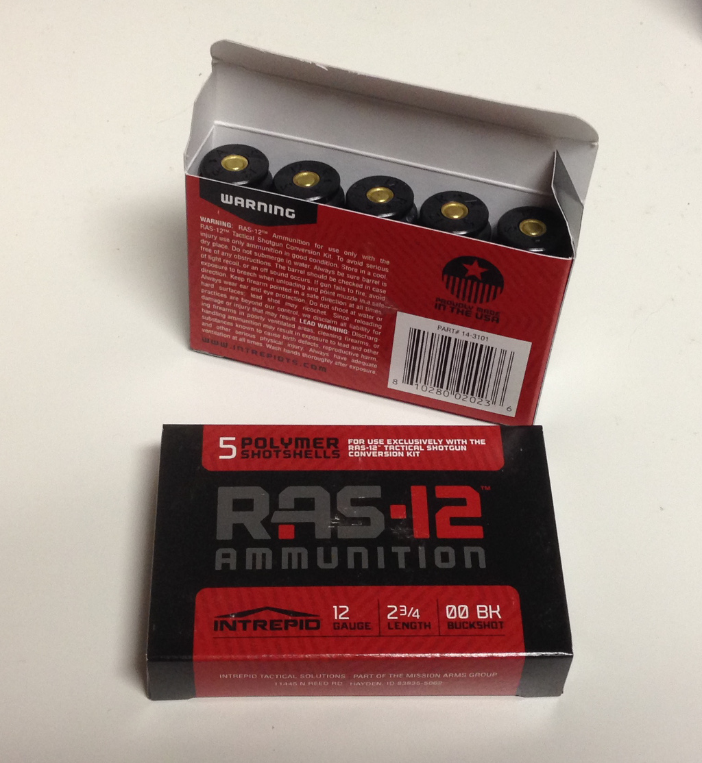
The ammunition comes in boxes of 5, with 20 boxes to a case.

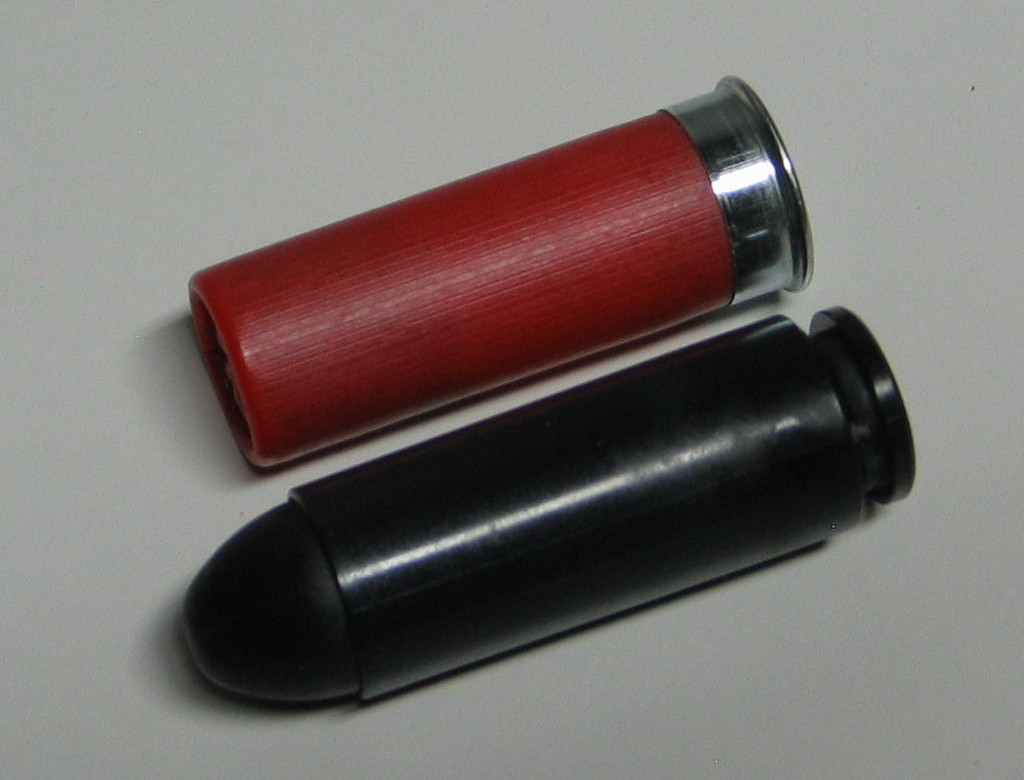
The cartridges look very little like a traditional shotshell, and very much like a modern rebated rim pistol cartridge.  In this manner, it is reminiscent of the .50 Beowulf cartridge designed for the AR-15 platform.  The rounded nose and rebated rim makes feeding far simpler than with a standard 12ga shotshell, and allows for easy adaptation of existing magazines.

The most significant feature of the cartridges is obvious – they are not of metal construction, but polymer (US patent 9109850 calls out polycarbonate and nylon as suitable materials, though various online sources specifically note polycarbonate as the hull).  This feature alone is what made me take notice of the system, given that I’ve done a bit of tinkering with 3D printed polymers in gunsmithing applications.  Even if supplies of the original ammunition dry up *cough* Gyrojet *cough* Dardick *cough* EtronX *cough* it should still be possible to recreate the cartridges in a reverse-engineered fashion.  I’m somewhat surprised that the RAS-12 designers didn’t opt to ‘open source’ the design, as SAAMI standardization is precisely what has allowed previously proprietary cartridges to survive in the market if not outright flourish.

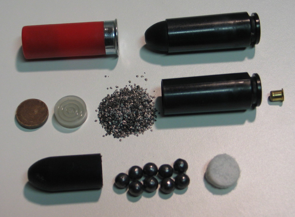
I carefully disassembled a cartridge to determine the weights (in grains) for all of the components:

  • Projectile half: 512.4 gr
    • Nosecone: 24.8 gr
    • Nine pellets of 00 buckshot: 481.2 gr
    • Wadding: 6.4 gr
  • Propellant half: 191.0 gr
    • Nitro card: 13.0 gr
    • Gas seal: 17.0 gr
    • Powder: 29.0 gr
    • Hull: 117.2 gr
    • Primer: 14.8 gr

…for a grand total of 703.4 grains for a fully assembled cartridge.  There’s certainly a bit of tolerance to these measurements, but they should serve as a suitable starting point for weights.  Now, to start measuring the hull and nosecone to draw up in CAD…

4-jaw chuck for the Keiyo Seiki

I recently had another Keiyo Seiki/Homach lathe owner contact me, and I mentioned that I had been meaning to get around to posting a copy of the manual that came with my machine.  It turns out that other owners have been looking for one, so hopefully this helps a few people: Keiyo Seiki Homach KM-1800C […]

I recently had another Keiyo Seiki/Homach lathe owner contact me, and I mentioned that I had been meaning to get around to posting a copy of the manual that came with my machine.  It turns out that other owners have been looking for one, so hopefully this helps a few people: Keiyo Seiki Homach KM-1800C lathe manual

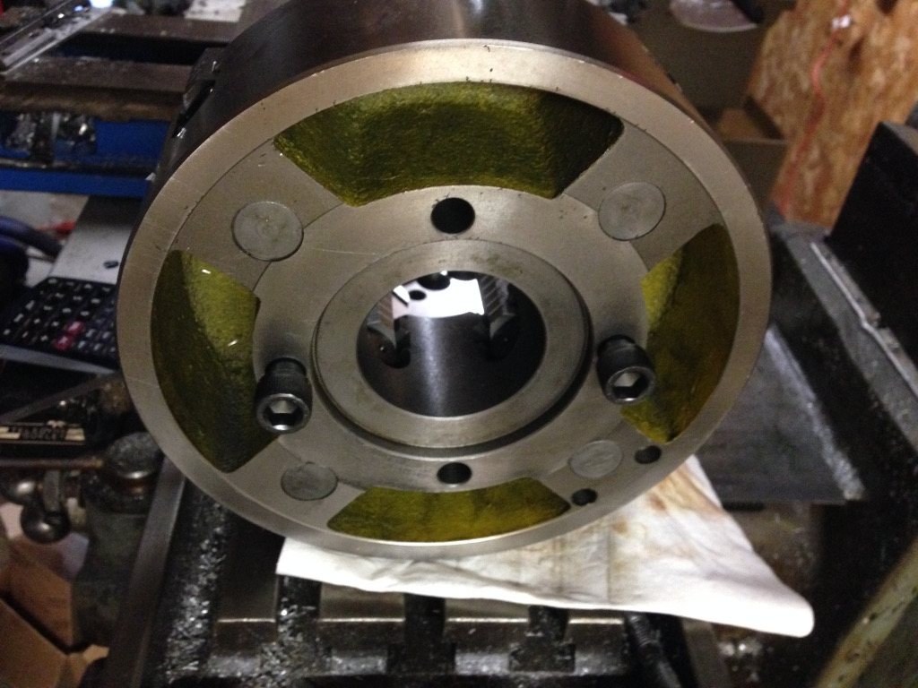
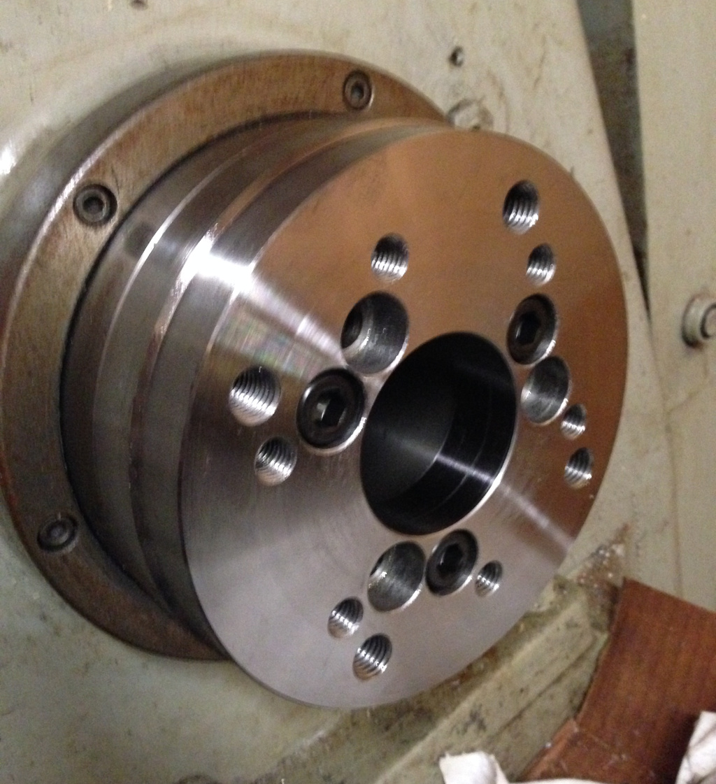
When I purchased my lathe, it came with both a 3-jaw and a 4-jaw chuck – the 3-jaw was mounted to the headstock and the 4-jaw was in a box.  However, the first time I wanted to try using the 4-jaw, I discovered that the chuck uses a D-6 camlock mount, not the A-6 mount that the lathe spindle actually has.  Apparently I had been given the incorrect chuck, but it had been long enough that I didn’t have the seller’s information anymore.

My first thought was to see if I could somehow mount the 4-jaw with an adapter plate of some sort – the jaw body itself mounts to a ‘spider’ that has the camlock lugs on it, so all I would need to do is to replace the spider with a backplate.  Well, in an ideal world, that would be the case.  The screws that attach the spider to the chuck body are attached from the spider side, not from the front face of the chuck.  Thus, using an adapter plate would be a mechanical impossibility with no way to reach the attaching screws.  So now I have a D-6 4-jaw that needs a new home, and I needed to start from scratch.  Off to Enco!

Enco did in fact have the sort of 4-jaw chuck I was looking for (I selected it based on the size of object it could pass – anything smaller than the headstock ID would be wasteful), so I purchased it during one of their free shipping promotions.  All I needed then was a backplate, which I procured from “Industry Recycles” on Ebay.  I think it was actually an Enco offering but I managed to snag it for about half price.  Score!

Unlike the backplate for the 5C collet chuck, this backplate mounted up just fine.  The trick, then, was mounting the chuck to the backplate rather than mounting the backplate to the lathe.  Mounting hardware was easily purchased from McMaster-Carr, and then it was time to start making holes in things.

Given my experience with the 5C collet chuck mounting, I decided to be a little more precision oriented this time around.  I started by measuring the hole locations on the chuck itself.  Using calipers and screws inserted into the mounting holes, I measured the distance across each pair of screws (both ‘inside’ and ‘outside’ measurements).

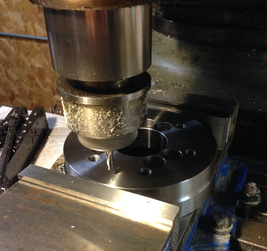
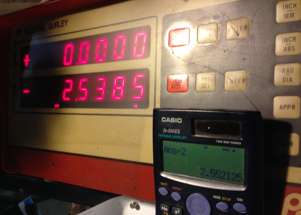
I found that the locations of the four mounting bolt centerpoints differed by about 5 thousandths of an inch.  Instead of just basing my cuts on a single measurement, I opted to use the average instead, which came out to be a bolt circle of 5.10425″, or a radius of 2.552″.  Easy work – put the backplate in the vise in an orientation that will clear the existing holes, indicate the center bore, and drill 4 holes at +X, -X, +Y, and -Y locations of 2.552″.

Wait, the Y handwheel stopped….

Noooooooooo!  I ran out of travel little more than an eighth of an inch from the lowest hole location.  I started to resign myself to moving the vise to a new location on the table (I hate having to re-indicate in a vise almost as much as tramming the head), when I realized “duh, just rotate the hole pattern by 45 degrees”.  So each hole would be at X/Y +/- 1.8045″.

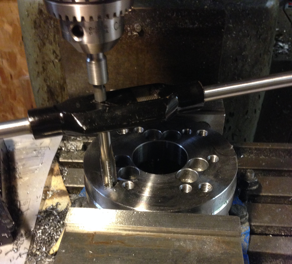
After drilling, I ran a M14x2.0 tap through the holes.

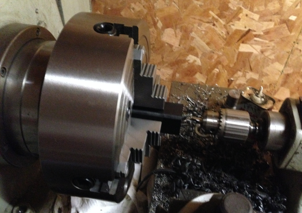
The backplate mounts just fine to the lathe spindle….

And the 4-jaw mounts just fine to the backplate!  I started right in on drilling some Delrin for a new product offering.

PIR foam for Stratasys build trays

Filament is the primary consumable on Stratasys machines, but not the only one – the build trays are also considered consumable.  On newer machines that use plastic trays, the official recommendation is to use them for only a single print, but that starts getting expensive fast, so users will wipe them down with acetone or […]

Filament is the primary consumable on Stratasys machines, but not the only one – the build trays are also considered consumable.  On newer machines that use plastic trays, the official recommendation is to use them for only a single print, but that starts getting expensive fast, so users will wipe them down with acetone or try sandblasting them to freshen up the surface for more use.  The old FDM series machines that I have don’t use plastic trays as a build base, but rather a foam square.  I had already investigated alternate materials with poor results, and John Branlund had started to look into craft store foam instead, as it seemed to be the material to beat.  We eventually concluded that the foam is most likely General Plastics FR-7104 modeling foam based on the sample kits that the company provides.  I haven’t pursued this further, however, as I can’t imagine that shipping on a 4’x8′ sheet of rigid foam could be anything close to ‘low cost’, and I have about half a dozen extra foam bases anyhow.  However, I’ll be turning the FDM 1600 loose to be used by other Makerspace members very soon, and I’d like to give them the ability to simply replace the foam bases as they deem necessary without burning through what I have left.

Some time back, fellow Makerspace member the_digital_dentist was experimenting with various slurries and sprays to improve part adhesion on his very large scratchbuilt 3D printer.  I gave him a Stratasys foam base to try, and it worked like a champ (almost too well, since the ABS support doesn’t break away nearly as easily as HIPS support).  I mentioned my woes in trying to source more of the foam, and he suggested trying the foil-sided polyisocyanurate (PIR) foam that you can find at some home improvement stores, and gave me a few pieces to try.  I cut a 12″ square, peeled the foil from one side, and sprayed the other side with 3M 77 adhesive before pressing it onto my material testing plate.  I put the tray into the machine and let it heat up before testing it.

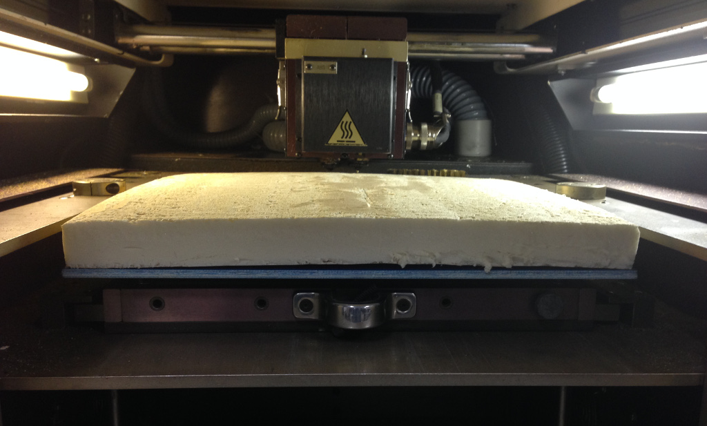
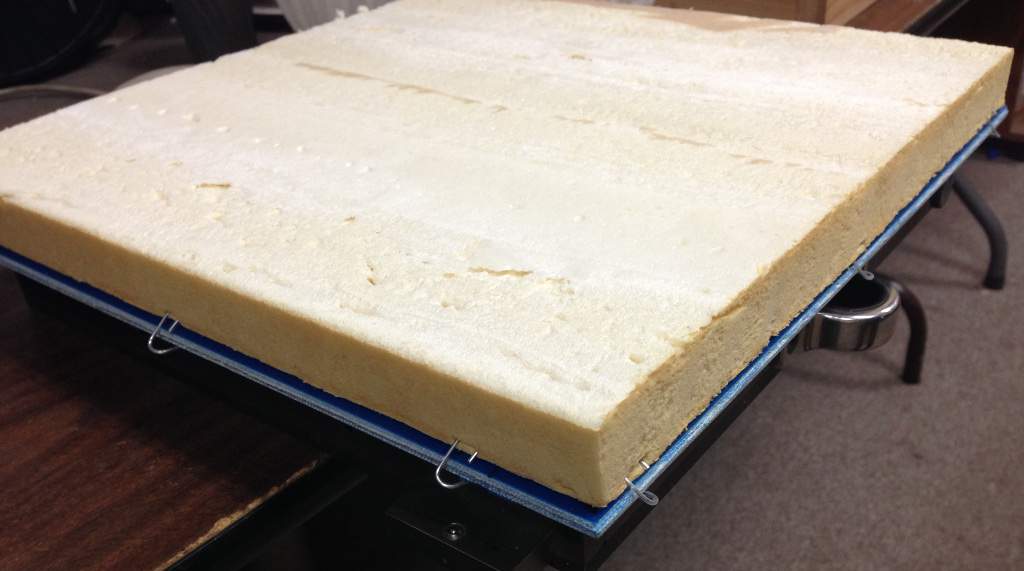
Unfortunately, I failed to take differential thermal expansion into consideration.  With the chamber heated to 70 C, the foam expanded ever so slightly, buckling upwards due to the foil still being attached on the underside.

I removed the foil from the underside, and lacking anything better, used a bunch of paperclips around the perimeter to secure the foam.

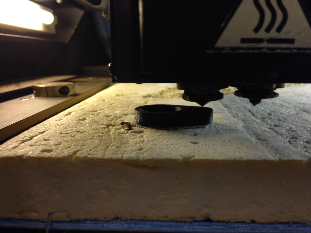
While the PIR foam surface isn’t as smooth as the Stratasys bases, it’s ‘good enough’ for my needs and a test print went fine.

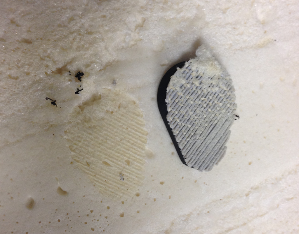
The part and support removed from the PIR foam very easily with just a little tearing of the substrate.  Overall, it’s still not quite as good as the FR-7104 foam (tears more easily and doesn’t grip as well), but for a cheap, readily available material, it’s the best thing I’ve found so far.  The only drawback is that locally available sheets are only 1″ thick and I need 1.25″ of thickness, but shimming up the base from the bottom shouldn’t be much of an issue.

FCG pocketing with CNC

A long-running project I’ve been tinkering with occasionally over the years has been machining an AR-15 lower receiver from scratch (or more precisely, a raw 0% forging).  I’ve made a fair amount of progress thanks to the excellent video done by Frank Roderus (which is a great machining tutorial even if you have no interest […]

A long-running project I’ve been tinkering with occasionally over the years has been machining an AR-15 lower receiver from scratch (or more precisely, a raw 0% forging).  I’ve made a fair amount of progress thanks to the excellent video done by Frank Roderus (which is a great machining tutorial even if you have no interest in firearms) as well as the Ray-Vin machining tutorial.  However, it’s really slow going, and I’ve made a few small mistakes.  Completing an 80% lower seemed like a good way to feel like I’ve accomplished something and would be a nice CNC project.

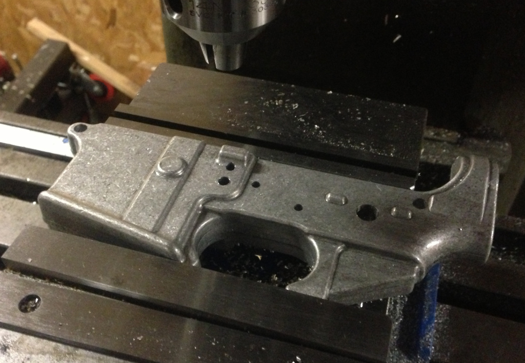
Drilling the holes for the takedown pins, selector, hammer and trigger pins, etc. is pretty straightforward after planing the top surface of the forging.  For an 80% lower, the takedown pin holes are already drilled and you can just use a drilling jig to drill out the holes on a drill press.  Call me a purist, but I still prefer just putting the lower in the mill vise as above, indicating from the front takedown pin hole, and drilling the rest of the holes with positions called out with the DRO.  The jig is invaluable for the various milling operations, though.

While the jig works great on the big manual mill, I can’t exactly clamp it into the diminutive vise on the CNC Taig, so I needed to determine a way to secure the fixture to the Taig table.

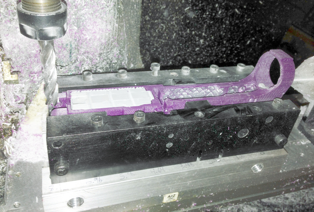
The 10-32 tapped holes on the A2Z tooling plate I use are spaced at 1.16″ intervals, and it turns out this spacing could be accommodated by the CNC Gunsmithing jig I use.  I drilled a line of holes for 10-32 clearance on the right jig half, and three 1/4″ holes on the left jig half (I used larger holes on one side to allow for slight differences in receiver thicknesses).  The magwell and trigger guard still stick out from the bottom of the jig, so I use a par of 1″ square bars on either side to raise everything up.

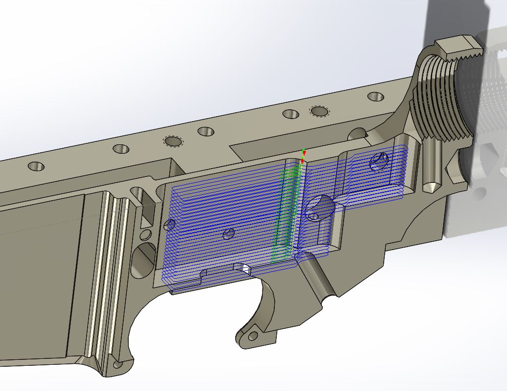
Generating G-code was pretty straightforward – I used HSMExpress to generate a path for the upper ‘shelf’ and a second path for the rest of the pocket.  Yes, I tend to make Z-steps very shallow, but hogging out material with a 3/8″ endmill with a fairly long length of cut is quite a bit for the Taig to handle, so I try to keep all the cutting lightweight, even if it means really long cycle times.  This was my first attempt to use HSMExpress, and I had no idea how well the toolpaths would work, or if the mill would suddenly take off on its own and carve a giant trough through the piece, turning a $70 part into 62 cents of scrap metal.  If only I had some sort of cheap plastic version for proving out the setup…  Quick, to the 3D printer!

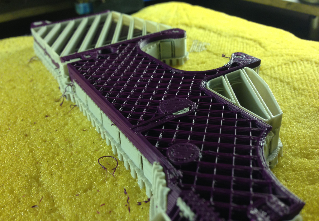
I took a standard AR lower CAD model and filled in the FCG area to simulate an 80% lower.  I made sure to print the part with sparse infill to save plastic and time, but I still needed a way to have a ‘solid’ FCG area to provide material for the mill to actually cut.  I cut an opening over the FCG area and mixed up a batch of West System epoxy (I wish every hardware stored carried bulk epoxy supplies – luckily I live near one) loaded with a whole bunch of talcum powder.  I could have used some other filler, but I went with talc specifically to give minimal wear on the cutting tool – many common epoxy fillers can be quite abrasive (to say nothing of the fiberglass, carbon fiber, etc. that generally constitutes the matrix of a composite material layup).  I poured the epoxy/talc mix into the FCG area and let it sit overnight to cure.  In retrospect, I should have tried doing a vapor treatment on the part first, as the epoxy seeped out the sides a bit, but it wasn’t enough to affect the part’s purpose.

After reaming out the takedown pins, I was able to mount the printed 80% lower in the jig bolted to the Taig’s table.  I ran my generated program, and it worked great!  Right up until the very end, when the mill plunged right through the rear of the bolt catch area.  Precisely the sort of thing I wanted to test for, so it was all worthwhile.  I made a few adjustments to the G-code and ran the program through again to make sure that nothing else looked awry.

After that, I switched out the printed plastic lower for my partially completed 0% lower.  This showed me some other issues I hadn’t anticipated, specifically that the endmill liked to bog down in the aluminum.  I hit STOP right away, turned off the spindle power and took a step back to ponder.  The 4-flute endmill was probably not the optimal tool for this pocketing operation, but I had gone with it to increase rigidity due to the long tool length required.  The default toolpaths were also using climb cutting rather than conventional paths – this should result in less power required, but I’ve had bad luck before with climb cutting on the Taig and wanted this pocketing program to ‘just work’ even if sub-optimal.

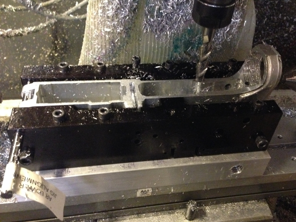
With those changes made to the program and the purchase of a 2-flute endmill, I felt confident enough to subject a purchased 80% lower to the gauntlet.  One thing that proved very helpful were a pair of 1/4″ ground drill rods from McMaster-Carr that I could slide through the takedown pin holes in the left jig plate all the way through the holes in the lower.  This helped keep everything perfectly aligned while tightening down all the screws, and then I also used the rod to indicate in my X-axis position with an edge finder.  Make sure to remove the rear rod before starting the machining operation, though, as it sits right in the area to be machined.

Gripping a WD-40 sprayer in one hand, and Shop-Vac hose in the other, I exhaled deeply, turned on the spindle, and hit the green Start button in Mach3.  This operation makes a lot of noise, and I worried that something would seize up eventually, but my revised toolpath (I used a slightly different step-down path between Z-levels as well) seemed to do the trick.  When the program finished and the spindle fully retracted, I had no unintended cuts on the part and a nice, bright, shiny FCG pocket.

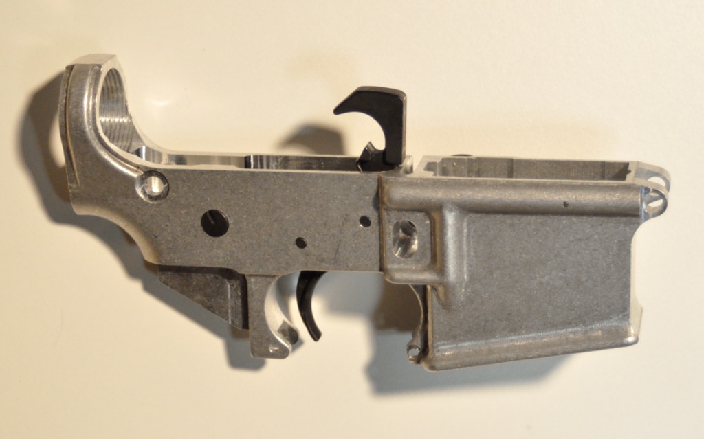
After washing it off, I installed the FCG components and did a safety check (make sure it will not fire if the safety is engaged, make sure the disconnector is working properly, etc).  Everything functions perfectly!  I’ll do a bit of identification engraving on the lower, and then it’s time to start picking out anodizing colors…

A pair of quick machining projects

It’s been a busy summer/fall/early winter, but I’ve managed to make a few chips in the shop over the past few months.  First up, dad had a front tractor axle that needed a little work.  The hole drilled through it wasn’t quite at the needed 5 degree angle to allow for proper assembly, so he […]

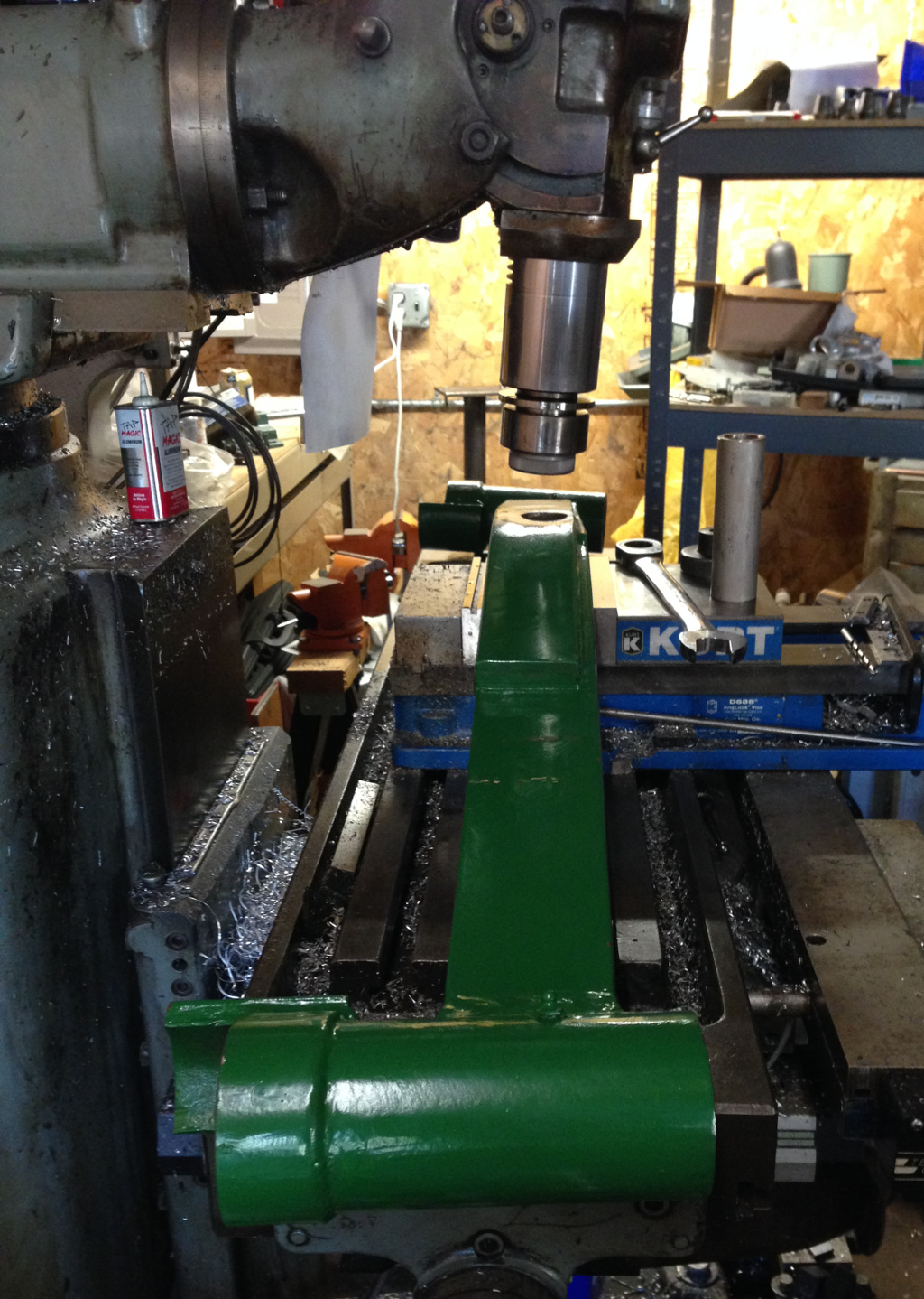
It’s been a busy summer/fall/early winter, but I’ve managed to make a few chips in the shop over the past few months.  First up, dad had a front tractor axle that needed a little work.  The hole drilled through it wasn’t quite at the needed 5 degree angle to allow for proper assembly, so he ground out the sleeve that had been welded in and I gave the boring operation a try.

Clamping the part was a little easier than I thought it would be.  It’s a heavy beast, and is as long as the entire mill table.  There’s a pair of blocks near either end that worked great for aligning it on a a horizontal plane, then I just had to clamp the center section in the vise.  I tipped the head forward by 5 degrees to complete the setup.

I seem to have lost the feeler clamp screw for my trusty Blake Co-Ax indicator, so I used an edge finder to pick up the hole center instead.

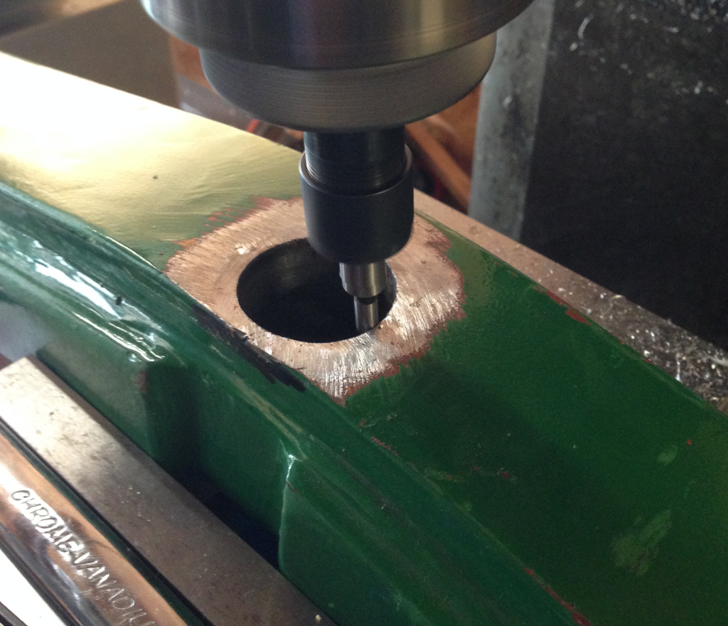
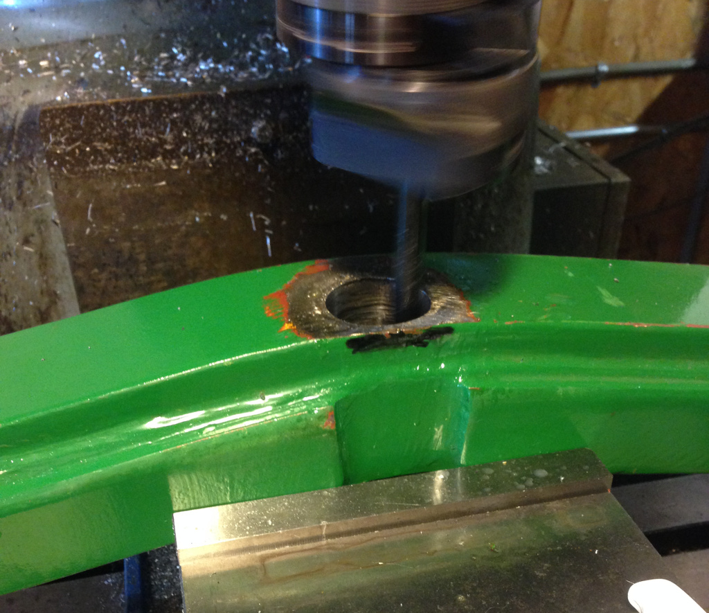
I didn’t have a boring bar long enough to plunge all the way through, so I bought one just for this project.  I selected a bar tipped with C2 carbide since the cut would be interrupted due to being a slightly different angle than the original hole.  I started by setting the boring head to a small enough diameter that it would just start cutting at the bottom of the hole (where the offset between the existing hole and my new cutting axis is greatest).  I then adjusted the boring head to make the hole a little larger, set the powerfeed, and bored again.  It was long, slow work, but I finally got to the point where I had better than 50% circumference all the way through.  Finally, I turned a matching sleeve on the lathe that dad could weld into the axle hole for the whole assembly to ride on an axis pin.

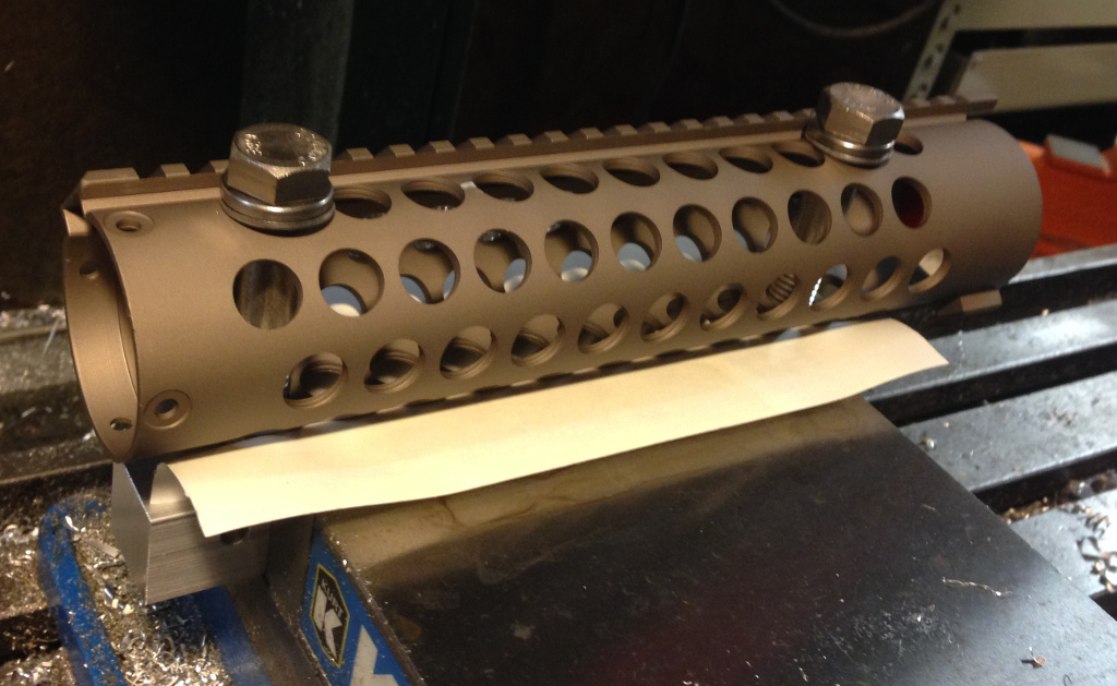
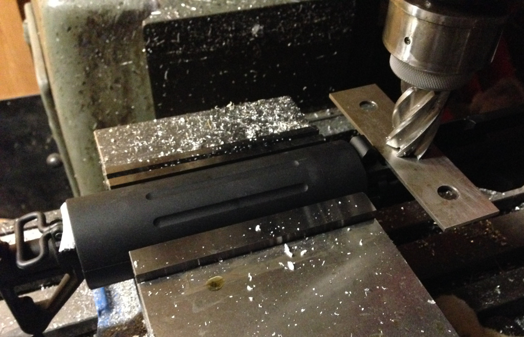
A friend is assembling a new upper for his AR, and one of the components is a Sentry 7 adjustable gas block.  Unfortunately, the freefloat handguard he’s using makes adjustment of the metering setscrew almost impossible.  Dremeling out a simple slot would fix things just fine, but would look pretty ugly – milling the slot would look much cleaner.

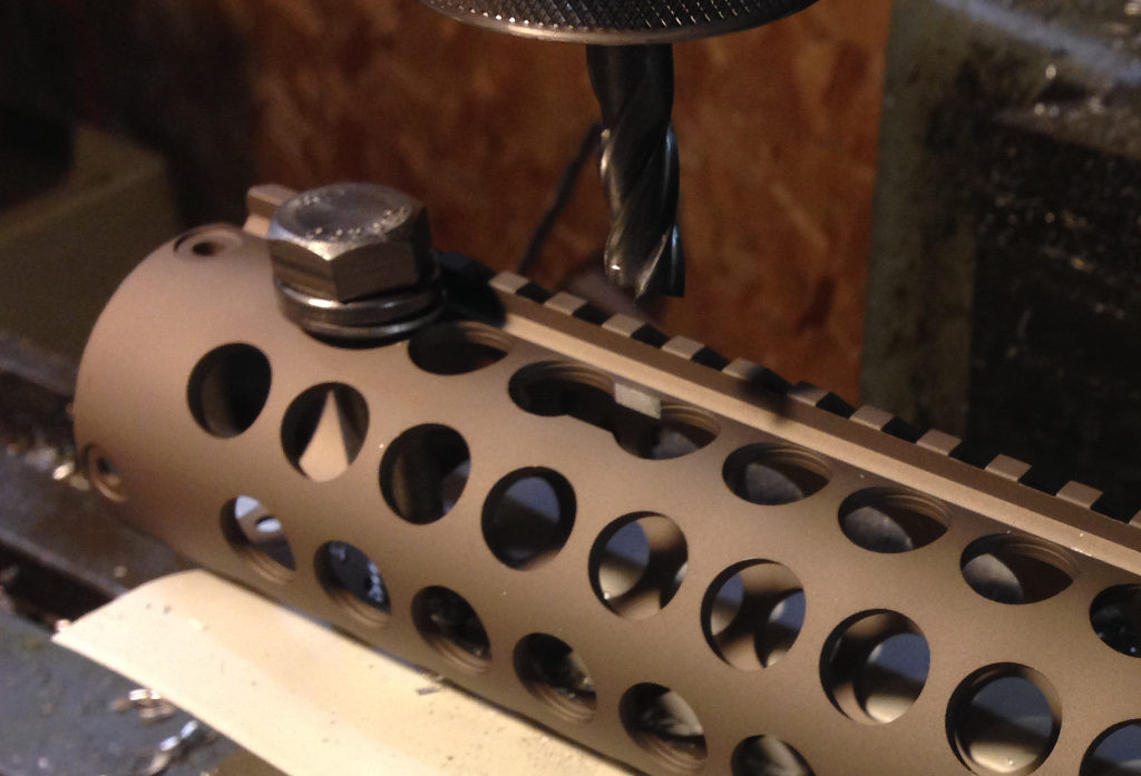
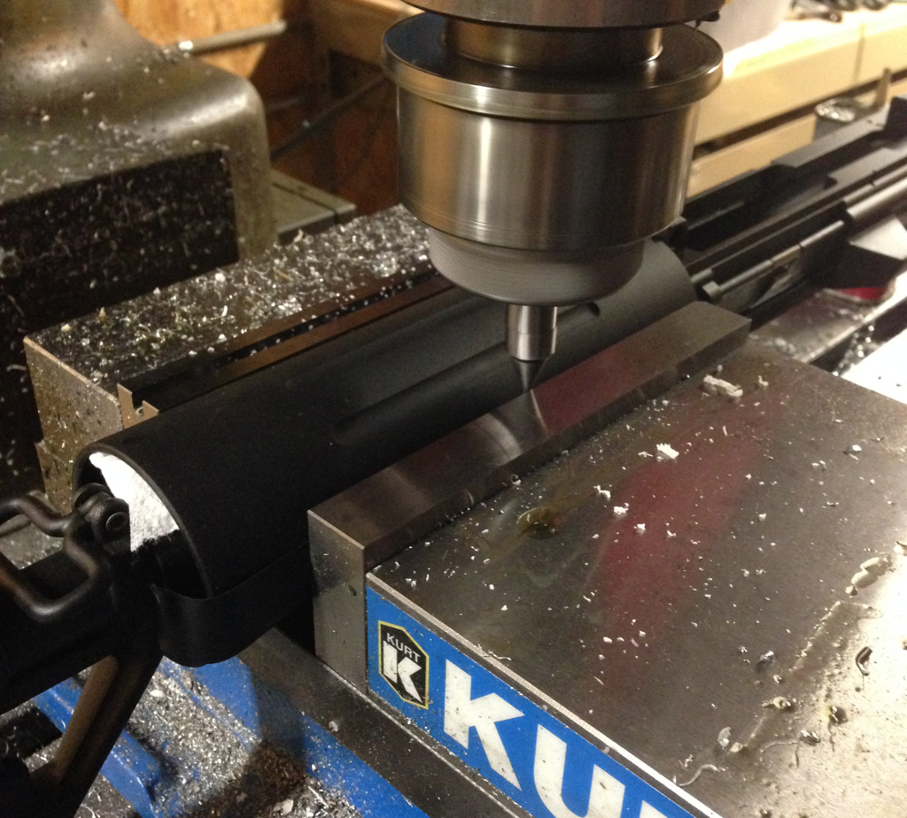
The problem is, how do you clamp a round object while also properly indicating it so the cut is right over the central axis?  After a bit of pondering, I came up with the above solution.  I first drilled and tapped holes in a 1″ square aluminum bar and clamped that into the mill vise.  I used strips of tape on the vise jaws to protect the anodizing on the handguard, and then used a pair of 1/2″ bolts to secure the handguard – tightening the bolts works to wedge the handguard against the top edges of the jaw faces, perfectly centering and aligning the handguard.

At that point, milling the slot (really just removing the web from between two holes) was a piece of cake.

Aviation

Perhaps I haven’t mentioned it a great deal on my blog, but I guess I should come out and say it if anyone is wondering: I love airplanes.  I suppose I always have.  Growing up on the shore of Lake Michigan, our house was under a frequently used training flight path for C-130s and A-10s, […]

Perhaps I haven’t mentioned it a great deal on my blog, but I guess I should come out and say it if anyone is wondering: I love airplanes.  I suppose I always have.  Growing up on the shore of Lake Michigan, our house was under a frequently used training flight path for C-130s and A-10s, and the sounds of Hercs or Hogs was enough to send me running outside to see what was passing overhead.  Some of my favorite early memories are of spending time at EAA Oshkosh with my uncles and grandfather on a foggy summer morning.  I distinctly recall seeing sometime in the very early 1980s an F-14 flying with wings swept in formation with a group of WWII warbirds (it may have even been a full Grumman ‘cats’ formation), then pulling out with an immense roar in the most memorable ‘missing man’ formation I will ever be witness to.

As a kid, I actually got kind of annoyed when going to the EAA airshow – I really wanted to see the jet fighters, but my uncles always dragged me first to see the WWII warbirds.  To be honest, I didn’t see their fascination with those old, propeller driven machines, when there were fast, exciting F-15s, F-16s and other such cutting edge combat planes as seen in An Illustrated Survey of the West’s Modern Fighters to look at (I swear, I absolutely devoured that book).  Many years later, I finally came to realize that it wasn’t a fascination at all – it was a deep respect and reverence for the planes and what they had accomplished so many years ago.  Now, when I go to that very same airshow, it’s not the modern jets that I go to look at first – it’s those old warbirds that so enraptured my uncles and grandfather.  The sound of a P-51 equipped with a Merlin V-12 is simply as magical as its engine name would imply.  Seeing the majority of airworthy P-38s in existence lined up together is the very best reunion imaginable.

I still love the jets, of course.  Oddly enough, many of the jets I knew and was fascinated by as a kid are now parked in that same warbird section – you might see an F-4, a MiG-21, or even a Sea Harrier in that area.  Sadly, with heavy restrictions now in place on what can be sold off into the civilian market, it seems quite likely that in another 10 or 20 years, there will still be more WWII vintage planes flying than the fighters I grew up with.  Apparently the government thinks shredding its heroes is for the best, and don’t even get me started on the USAF curtailing practically all airshow participation due to budget cuts (or so they claim – meanwhile, Canada was happy to send a few warplanes and even their phenomenal jet team to the Rockford air show).

Beyond my childlike desire for the sound of afterburning turbofans, I simply love airplanes in general.  I’m one of those weird people that simply have to look skyward when they hear something passing overhead, no matter how pedestrian.  I’m not even very good at being able to tell what type of plane it is.  It’s flying in the air, and that’s all that matters to me.  I’ve tried to scratch the itch – my bookshelves sag with books about airplanes, my hard drive is packed with flight simulators, and I have a pile of RC planes (and parts of RC planes, but I suppose that’s to be expected).  And yet it simply has never been enough.  I need to fly for myself.  I find it absurd that the concept of ‘aviation’ can be encoded into one’s DNA, yet the similar fascination of my uncles and grandfather appear to serve as at least anecdotal evidence that perhaps such desire is more rooted in one’s being than might normally be considered.  To be slightly more blunt, perhaps aviation is indeed in my blood.

I’ve been saving up for several years for flight training.  Flying isn’t cheap – despite the dreams and aspirations of optimistic 1950s post-war America, it’s not something you can pursue on a whim (and expect to succeed), unlike getting a motorcycle license (2 Saturday afternoons of training, a DMV test, bam – you can ride a bike).  I’ve heard that getting a private pilot certificate today actually requires more time/training than getting a commercial rating 50 years ago.  Despite the cost, I knew that this was something I simply had to pursue.  Stephen Force is an utter poet of piloting and has about the best summation that I can possibly imagine – “what do you owe to your 10-year-old self”.

No matter who who are or what are your own passions, I think this is a remarkably succinct distillation of what your true pursuits as an adult deserve to be.  If you had a time machine and visited yourself at 10 years old, what would disappoint them most about you?  Seriously consider that for a moment – looking at not a stranger, but yourself, 10, 20, 30, 40, 50, 60…  however many years younger than you now are.  What would you have to admit to your own self that you hadn’t even attempted, much less accomplished?  In my case, it would be “why didn’t you ever become a pilot?”  I would have to tell my 10 year old self that I had always wanted to, but you know, never quite got around to it, or some other bullshit answer.  And my 10 year old self would have looked at me with the most utter disdain imaginable.  They… you…  had dreams unrealized.  The opportunity was right in your face, yet you never grasped it.

I finally realized that in some way, I had made a promise to myself long ago.  I was going to either become a pilot or make the very best attempt at it that I could.  Your 10 year old self still lives inside of you, after all, subdued though they may be.  And I wasn’t going to let mine down.

Today I hope I did the 10 year old that lives inside of me proud.  I can’t verbalize the experience in any meaningful way, so I hope a simple log entry will suffice.

6 SEP 2014 – First solo – J-3 N42522

Carbs

A few weeks ago I finally got the GS500 running for the season.  I rode with friends out to Madison and around the Kettle Moraine area as shakeout runs for a trip from Milwaukee to Minneapolis in a few weeks (should be interesting on little 500-650 cc bikes).  My bike, while it worked, needed some […]

A few weeks ago I finally got the GS500 running for the season.  I rode with friends out to Madison and around the Kettle Moraine area as shakeout runs for a trip from Milwaukee to Minneapolis in a few weeks (should be interesting on little 500-650 cc bikes).  My bike, while it worked, needed some attention.

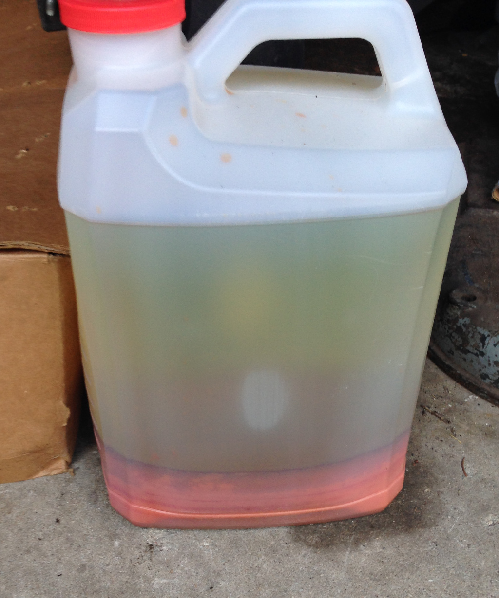
That’s the contents of my gas tank after draining it.  I’m surprised it ran at all – I needed to drain an entire Starbucks cup (thank you, parking lot litterbugs) worth of crud out of the float bowls in order to get home from Madison.  The second issue was the choke – it’s been getting progressively stickier until our 4-person ride to Kettle Moraine, where it seized entirely in the open position.  At stoplights I got to look like a tremendous jerk with my bike idling at 4000 RPM (and a Vance & Hines exhaust to boost the noise even further).  So after the ride I knew it was time to really dive into the bike guts.

After pulling the tank (and discovering the red-brown horror within), I removed the airbox and had a look at the carb itself.  The core issue was plainly obvious – a bent plate and choke plunger end on the left side.  So, just bend the end of the choke plunger back into pla… *snap*

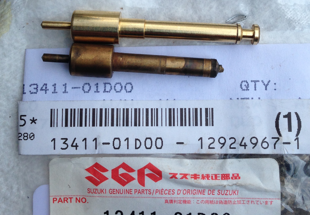
Well, dang.  Fortunately, there’s a Suzuki dealer just down the road, and 2 weeks later I had a replacement plunger in hand.  Once I went to install it, though, something wasn’t right.

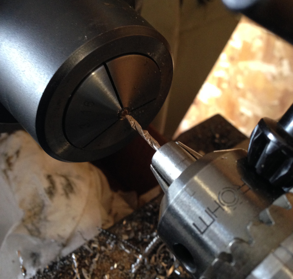
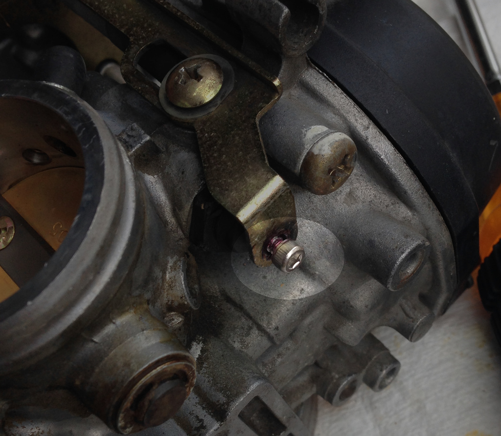
Yeah, the new plunger (top) was a bit different.  I don’t have another 2 weeks to get the correct part (if the shop can figure out the right part number), so I chucked the old plunger in the lathe.

A #43 drill and a 4-40 tap provided the threads I was after.  I installed the plunger back into the carb, and attached the plate.  A loctited 4-40 socket head cap screw finished off the assembly.

The carb, airbox, and most hoses are now reattached.  Once I put the gas tank back on and put fresh fuel in I’ll see if everything works.

Finally, a semi-working FDM 2000

Continuing from the previous installment… Even after thoroughly cleaning out the problematic support nozzle with appropriately sized tiny drill bits from either end, the nozzle would still clog and jam.  I did indeed have a single spare T12 (0.012″ orifice) nozzle, and installing it exorcised the demons that have plagued the machine for the better […]

Continuing from the previous installment

Even after thoroughly cleaning out the problematic support nozzle with appropriately sized tiny drill bits from either end, the nozzle would still clog and jam.  I did indeed have a single spare T12 (0.012″ orifice) nozzle, and installing it exorcised the demons that have plagued the machine for the better part of a year.  *sigh*  It’s always the last thing you suspect.  Frankie notes that when he had nozzle clogs, he used a torch on the nozzles as a ‘take no prisoners’ approach to cleaning out foreign matter.  I think I’ll have to try this method if for no other reason than to exact thermal revenge.

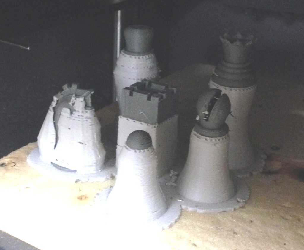
Last week, after verifying that both nozzles were feeding without any jams, I started a test print as a good ‘shakeout’ of the system.  Printing Duchamp chess sets are all the rage right now (more on that in an upcoming blog post), so I thought it would be a good inaugural print.

When I stopped in at the Makerspace the next day, I was relieved to see that the print had completed successfully, and I didn’t have a chamber full of ‘3D printer barf’.  The print quality isn’t as good as I’m currently getting with my FDM 1600, but that’s to be expected since I have to fully calibrate the XYZ location of the support nozzle in relation to the model nozzle.  There’s also a fair bit of rippling in the prints that I think may be due to a slightly loose drive cable.  Finally, the layer adhesion is quite poor, but this is standard P400 ABS, not the MG94 (P430 ABS+) from Coex that has me absolutely spoiled (yet another upcoming blog post).

Gunsmithing without a 3D printer 2

A friend had a Bushmaster rifle that they wanted to add a bipod to – unfortunately, the freefloating handguard has no provisions for mounting a bipod and even more, the handguard is integral to the barrel nut itself.  Still, I’m always up for a challenge. To make things easier, I decided to leave the handguard/barrel […]

A friend had a Bushmaster rifle that they wanted to add a bipod to – unfortunately, the freefloating handguard has no provisions for mounting a bipod and even more, the handguard is integral to the barrel nut itself.  Still, I’m always up for a challenge.

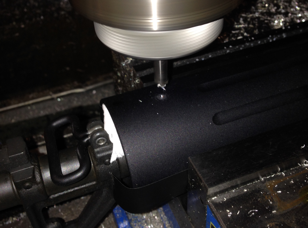
To make things easier, I decided to leave the handguard/barrel nut in place and put the entire upper on the mill.  This way I could use the upper receiver as my horizontal plane reference.  I stuffed toilet paper down between the barrel and handguard to catch any chips, and used a strip of electrical tape on either side of the handguard to keep it from getting dinged by the vise jaws.

My first thought was to use a test indicator in the spindle against the two flats on either side of the upper receiver’s bottom to get it aligned vertically, then I realized that a much simpler method would be to chuck a large diameter multi-flute endmill and bring it down against a parallel while loosely clamped in the vise.  Then tighten up the vise while keeping a little pressure on the quill to keep things aligned.  Viola, perfect alignment without a test indicator.

Next step was to find the centerline of the handguard.  There wasn’t enough clearance to use a cylindrical edge finder on the jaw faces, so I flipped the edge finder over to use the conical tip.  I just had to make sure to set the stop on the spindle so that I used the same Z height on each side.  Also, this wouldn’t have worked if the top inside edge of the jaw faces was dinged up, since using the conical end of the edge finder in this way gives only point contact rather than the edge contact that the cylindrical end would have provided.

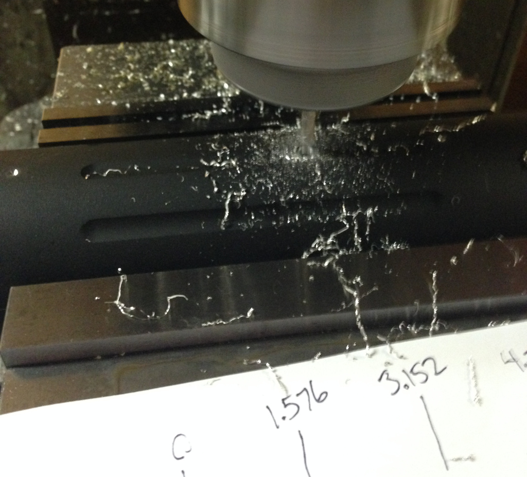
With the Y axis centered, I set my X axis zero as the end of the handguard and used a spotting drill to make a divot for the first hole 1.000″ in.

One of the ball end milled grooves on the handguard would be sitting right under the rail, but the groove is off-center by a little bit, so the spotting drill would be hitting the edge of the groove and not able to make a proper divot.  So for the two center holes, I used a 5/32″ endmill to punch holes all the way through (5/32″ is just a few thou smaller than the #21 drill used for the needed 10-32 threads).

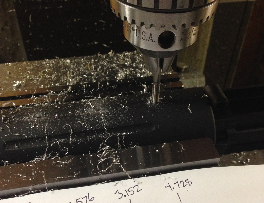
After drilling through all 4 holes, I put a 10-32 tap in the drill chuck and loosened the collet so I could spin the chuck by hand (but still have it perfectly positioned in the X-Y plane).

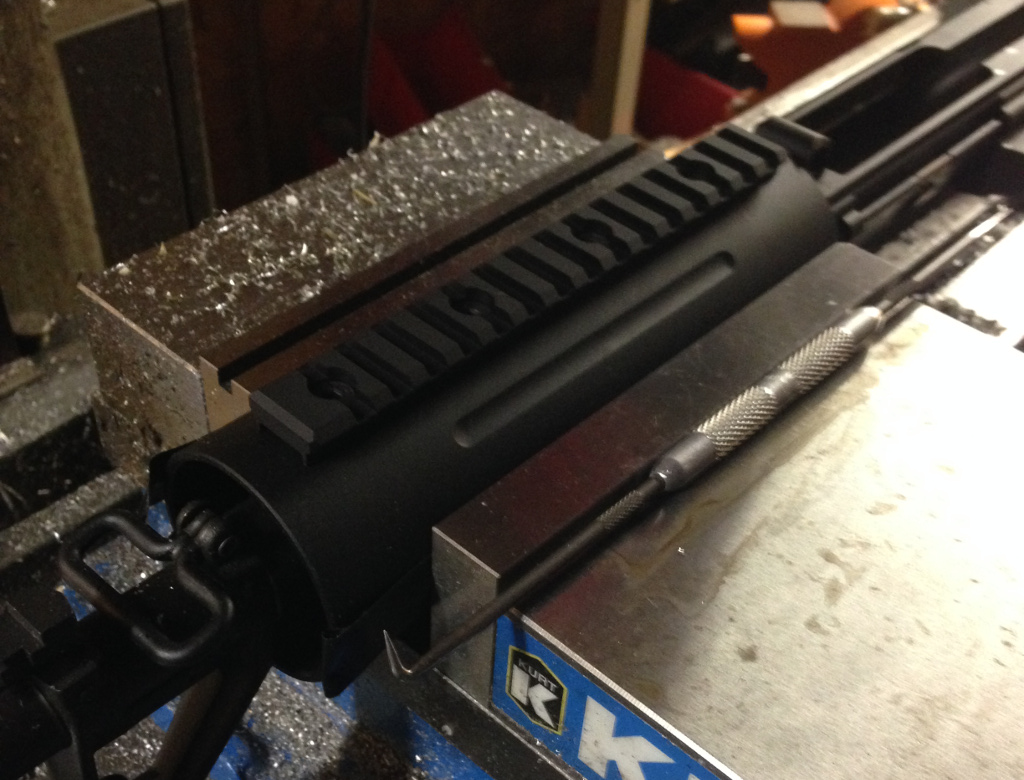
After using a pick to dig out the toilet paper from inside the handguard, I attached the rail, and everything fit perfectly.  Remove from the vise, blow out any straggling chips with compressed air, and the job is done!  Ideally the screws should be installed with blue loctite (the metal is thin enough that you have to be careful about not torquing the screws too much and stripping the threads), but since my friend wanted to maybe start with having two stub rails installed instead of one long one, I’ll let him deal with the threadlocker.