The Zcorp lives!

A few weeks ago, a sharp-eyed coworker mentioned that he saw a rapid prototyper on Craigslist that I might be interested in. It turned out to be a Zcorp Z402C powder bed machine (a technology developed at MIT, which lays down complete powder layers and fuses them selectively rather than depositing material in a specific […]

A few weeks ago, a sharp-eyed coworker mentioned that he saw a rapid prototyper on Craigslist that I might be interested in. It turned out to be a Zcorp Z402C powder bed machine (a technology developed at MIT, which lays down complete powder layers and fuses them selectively rather than depositing material in a specific path like my Stratasys). The machine came with a depowdering station and a wax infusion machine, which are nice bonuses – not all used Zcorp machines come with them. The machine was residing at a high school (which was blessed with a very nice technology program) and was currently inoperable (though had been mechanically sound when put into storage some 3 years ago).
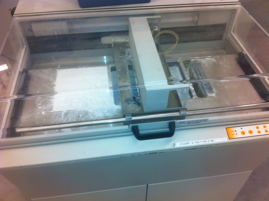
The Z402C has a powder supply on the left, which it wipes in a layer to the right (covered by the gantry) and then fuses the powder with an inkjet printer head inside the gantry. After each pass of the inkjet head, the supply is raised a little, the model bay is lowered a little, and a new layer of powder is spread.
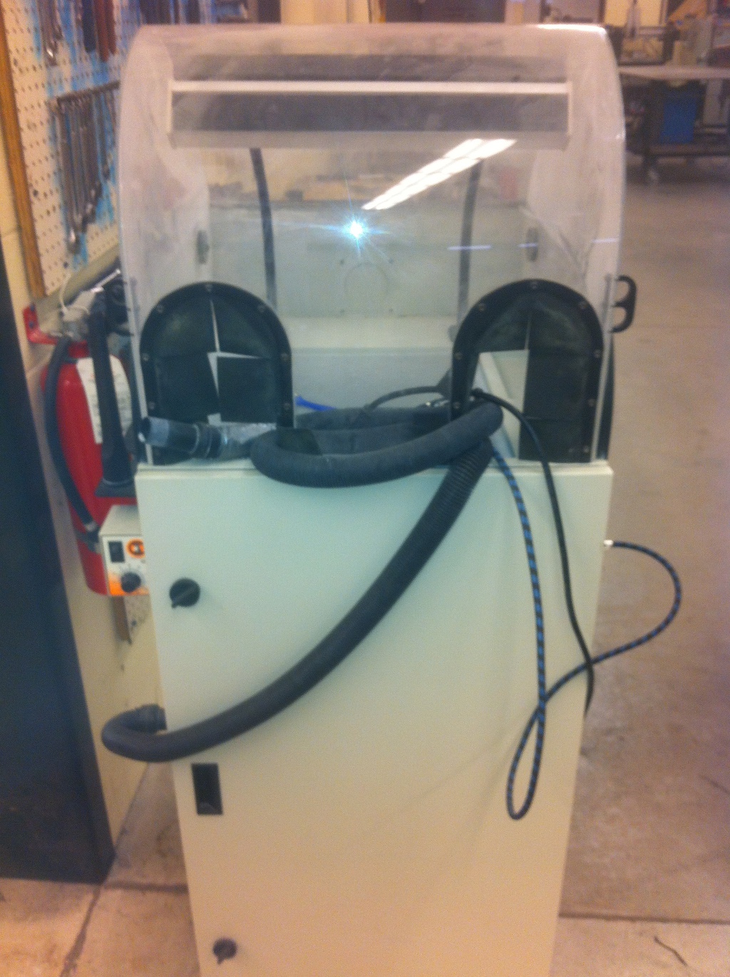
Once the part has been printed and is carefully removed from the loose powder (which is basically plaster in this case), excess powder is dusted off in the depowdering station, which is essentially a fancy sandblast cabinet. Within the cabinet are a very nice air compressor and vacuum - no hardware store grade stuff here.
After depowdering the part, it is still quite fragile and needs to be strengthened. This can be done by dousing it with superglue, though this can warp the parts. An alternative is to use this nifty wax dipper, which dunks the part into a heated bath of paraffin for a selected time.

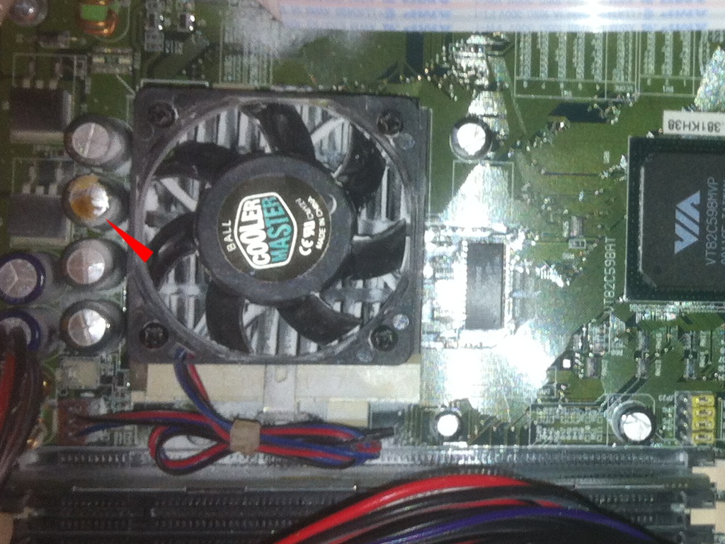
The seller said that they had diagnosed the problem to be a faulty motherboard (thankfully meaning a standard PC mobo, and not a custom proprietary PCB), and later, upon reviewing the photos I had taken when inspecting it, the issue jumped out at me:

Ho, ho!  All that ails the motherboard are some blown capacitors.  Getting this thing running seemed like a distinct possibility.  Just one problem – I really didn’t need (or have space for) another rapid prototyper, much less a powder bed unit.  But for a measly $500 for the whole system, I couldn’t just let it go.  Fortunately, I managed to convince Frankie (not that it took much arm-twisting) that it would be a perfect addition to the technology lab that he’s setting up for the art school.  Plus, much like with the Cole drill, I like knowing where I can put my hands on a particular tool, even if I have no use for it at the moment.  So I told the seller to consider it purchased, and I’d be by in a week to take delivery.

After replacing the trailer hitch on the truck as well as the long-missing passenger side rear view mirror, I had a vehicle that met U-Haul’s rigorous requirements for trailer rental (in retrospect, I could have pulled up on a moped with a ball hitch and they still would have gladly taken my credit card).  Loading the equipment onto the trailer was easy – being in a high school’s shop, there were plenty of kids to heave the stuff onto the trailer and strap it down.  Once at Frankie’s studio that evening, we had notably less manpower at our disposal, but Frankie and I managed to manhandle all 3 pieces into the lab with no casualties. Charles dropped by later, and we all surveyed the bounty of the haul. We found the original machine invoices, and I forget what it all cost, but it was well over $50,000 when new. There were a few bottles of binder, a box of powder, documentation, little odds and ends… But we still had a dead machine. I took the motherboard and hard drive home to source replacement caps and image the hard drive (I recall reading somewhere that it’s a good idea to have a backup image of your Zcorp’s drive). Meanwhile, Frankie found the exact motherboard on Ebay as a refurbished unit, and bought it right away for about $175. Expensive, but when dealing with decade old PC equipment, it can be hard to find specific items. At any rate, we can always replace the caps on the original in the future if the refurb unit blows up someday.

The other week, we all met again at the studio to install the replacement motherboard and flip the power switch for the first time.   I had wisely snapped a few photos of the cable connections before taking out the busted motherboard, so installing the new one and putting the drive back in place went quickly.  Powering on the machine didn’t work, though – after about 20 minutes I found that I had plugged a ribbon cable in 2 pins off – after fixing this, the power button actually functioned (interestingly, the power button connects right to the pins on the PC motherboard, which remains in full control – I would have expected some other power/monitoring board to control the system at such a base level).

After that, we had a machine that was powered on, but not actually doing anything.  We poked at it for a good long while, trying to coax it into doing the startup dance that the manual indicated it should be running (the video output that we hooked up really wasn’t of much help for anyone who wasn’t a trained Zcorp technician, but it did seem to indicate that the machine was at least reading some encoder feedback).  After much web searching, Frankie tried jumpering some photosensors to bypass them, and suddenly the machine began to move the gantry of its own accord.  Victory!

We still didn’t have a null modem serial cable to communicate to the Zcorp with (needed to actually download files to it for printing), so we called it a night, pleased that we had resurrected the beast.  This past weekend, Frankie managed to scrounge up the needed cable and set the machine running a few layers.  It still needs calibration, the water cleaning the binder lines needs to be flushed through, and the screws and shafts could use a bit of cleaning and lubrication, but it’s a very healthy start to what I hope will be a great machine for the lab.
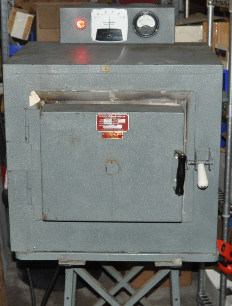
Hot stuff

I started building a Goodman-Holmes heat treat oven some years back, but never got terribly far with it, as I was to the point of puzzling over how best to cast the refractory cement (once the slabs are in place, the whole unit gets welded together, so replacement of the refractory is pretty much impossible).  […]

I started building a Goodman-Holmes heat treat oven some years back, but never got terribly far with it, as I was to the point of puzzling over how best to cast the refractory cement (once the slabs are in place, the whole unit gets welded together, so replacement of the refractory is pretty much impossible).  Plus, the refractory cement suggested in the book (sourced from McMaster-Carr) turned out not to be rated for direct contact with flame. I’ve since started looking more at just getting a kiln for the purposes of heat treating, as temperature control should be much more precise with an electric rather than gas system (plus never having to worry about running out of propane).

As such, I’ve been checking craigslist from time to time for kilns, and found one for $150 that looked like just the sort I’d find useful.  Roomy interior, front opening door, 220VAC power.  Little old lady drove it only to church on Sundays (actually, the seller’s aunt used it from time to time to fire ceramics – close enough).  Looked like something out of the 1950s and even smelled like the piece of vintage lab equipment that it is.  I bought it the next day and somehow managed to single-handedly manhandle it into the garage on its accompanying stand.

The only thing I’m not sure of is whether an electric kiln will be more cost effective than a gas oven.  Probably, but the mere fact that the unit has a much larger interior than the gas unit already puts it ahead.  It’s large enough to heat treat a big knife blade, which is a project I keep hoping to attempt one of these days (I’ve had the O-1 bar stock patiently waiting for me for a very long time).

After purchasing a length of appropriately sized (the meter goes up to a whopping 50 amps, after all) cable to form a suitable extension cord, I plugged the unit in and let it heat up.

It drew a constant 25A and I let the temperature climb all the way up.  Note that this unit has two temperature settings: on and off, depending on whether you have the cord plugged in or not (no power switch).

I thought “what the heck” and let the kiln climb as high as it liked.  At just over 2350°F the current draw fell drastically, which I figured was just some sort of transition point in the elements that caused a sudden increase in resistance.  Well, in a sense I was correct – driving the elements to failure will indeed cause them to break, and you can’t beat the resistance of an air gap.

I heated up the broken ends with a propane torch and twisted them together as per the notes at handspiral.com, but it looks like I have a lot of additional breaks to track down and repair.

Stupid broaching tricks

One of the little trinkets I sell in my online paintball store is nothing more than a modified stock part that adjusts the gun’s muzzle velocity.  The modification is straightforward – I simply drill a big hole through the middle to increase the airflow (just like porting the cylinder head of an engine, this improves […]

One of the little trinkets I sell in my online paintball store is nothing more than a modified stock part that adjusts the gun’s muzzle velocity.  The modification is straightforward – I simply drill a big hole through the middle to increase the airflow (just like porting the cylinder head of an engine, this improves efficiency) and then broach a hex through that hole so that the velocity can be adjusted with a hex wrench.  From the beginning, broaching the hex has been the fly in the ointment when modifying these parts.  The concept is simple enough – a hardened steel plug with a hexagonal cross section (and cutting edges shaped appropriately) is pressed with great force into a hole drilled the same diameter (or a teeny bit bigger) as the distance between flats on the hexagon.  The points of the hexagon carve into the circle, peeling six chips downwards along the walls of the hole.  In this case, I’m using an ‘F’ size drill bit (0.257″) and following up with a 1/4″ hex broach.

The problem with the broaching operation has been twofold – generating sufficient force to press the broach through the hole to the needed depth while at the same time keeping the broach as centered as possible with the hole it is cutting.  My initial method was to use a 5C collet fixture on the bed of the mill to hold the workpiece while gripping the broach in a drill chuck (with a short piece of metal rod as backing) in the spindle.  I’d crank down hard on the spindle feed lever (spindle not rotating – this is entirely linear) and plow the broach through the part with a fair bit of effort – while this worked just fine, I always felt like I was abusing the machine (though my buddy tells me he knows of a shop that punched metal parts in exactly this way on their Tree mill – they are certainly rugged).

As such, I’ve looked for alternative ways to broach the holes.  The most interesting method is rotary broaching, which is also more descriptively known as wobble broaching.  Some years ago in either The Home Shop Machinist or Machinist’s Workshop was a project for a nice rotary broach holder that could be fabricated out of mostly scrap with a bit of work.  Unfortunately, not only am I cheap, but I am also lazy.  The concept did give me an idea, though – the Taig headstock now comes standard with an ER16 spindle.  If I could simply bolt a headstock to the toolpost on my lathe, I’d be set.  I ran the idea past Nick Carter, who agreed that the idea seemed sound in theory, so I purchased a Taig ER16 headstock from him.

Taig ER16 headstock and mounting plate

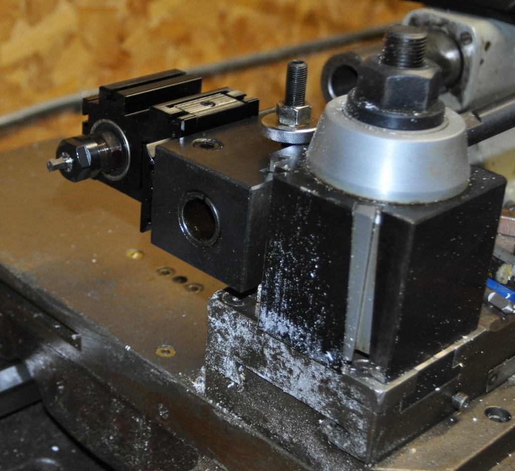
Ideally I’d make my own dovetail block to bolt the headstock to (the dovetail then mates to the quick change toolpost), but laziness got the best of me here (and then bit me as will be seen shortly) and I bolted the headstock to an unused boring bar holder.

Boring bar holder with mounting plate attached for the ER16 headstock
ER16 headstock mounted awkwardly on toolpost

Well, I overestimated the torsional rigidity of the toolpost mounting.  Really, I should have seen it coming – that’s a heck of a long moment arm between the centerline of the broach and the centerline of the shaft that bolts the toolpost to the compound.  When I ran the assembly into a part to be broached, the whole works just pivoted around the toolpost shaft, making a small (though roughly hex-shaped) indentation in the part.  The idea still has merit, I think, but even if I used a shorter block, I still worry that it wouldn’t be rigid enough.  I should probably think about mounting the headstock to the side of the toolpost so that there’s no moment arm to push it out of alignment.

I considered using the small arbor press I have to do the broaching, but it needs a more secure mounting to the benchtop, and I’d have no way to make sure that the broach is correctly centered with the part.  Unless, of course, I built some sort of system to always keep the part aligned with the broach…  Quick, to the scrap pile!

Alignment sleeve on top, with the broach and part holder underneath. Below that is the broach backup, the broach itself, and the part to be broached.

I dug up a piece of stout stainless tubing and some hardened shaft material that slid nicely through the tubing once I turned off a thou or so from one side (I love the big Keiyo Seiki – while the finish isn’t great on the cut areas of the hardened shaft, I wouldn’t have had a prayer of accomplishing such work on the 9×20 lathe).  The ‘from one side’ part is because I still haven’t addressed the 1.5 thou runout on the 5C collet chuck…  I made a short backup stop from a bolt to sit behind the broach – this let me adjust the depth of the broach without having to drill the hole in the broach holder to a precise depth.  Everything looked pretty good, so I stuck the broach in place with a bit of RTV silicone (I didn’t want anything too permanent).  I slipped a part into the part holder, then dropped the two holders into either end of the alignment sleeve.  Since the assembly looked a bit large for the arbor press, I threw the mess into the bench vise.

Broaching assembly pressed in bench vise

The part to be broached acts as a stop, so I merely needed to crank the vise down until I felt abrupt resistance.  After pulling the holders out of the sleeve, things looked like a success.

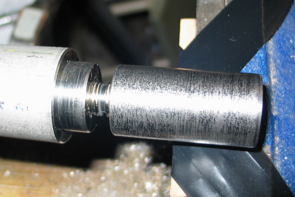
Broached to full depth

A little wiggling and the broach pulled out of the part easily.

The broaching on the part was superb – the chips were more symmetric than previous broaching done with the quill on the mill, and all that remained was to drill the chips out.  The batch of parts came back from plating on Friday, and they nearly sold out over the weekend.  Guess I better start making more.

Anno 2011

And now for another installment of “I should really get around to posting this one of these days”.  This summer’s anodizing class was cancelled (along with the pewter casting class) due to low enrollment.  Fortunately, the open sessions went ahead, so I managed to get my anodizing fix after all.  I wanted to try a […]

And now for another installment of “I should really get around to posting this one of these days”.  This summer’s anodizing class was cancelled (along with the pewter casting class) due to low enrollment.  Fortunately, the open sessions went ahead, so I managed to get my anodizing fix after all.  I wanted to try a few new masking techniques this time around, so I stuck to using the 3 same colors for simplicity.

For the left two samples, I masked the blue with UHU Por (sold in the US as UHU Creativ), which is similar to rubber cement but comes in a tube.  It masks just like rubber cement, but since you squeeze it from an applicator tip rather than brushing it on, you can make finer lines (of course, you could do the same with rubber cement in a blunt syringe).  On the top left sample, I masked the green by spraying some 3M 77 aerosol adhesive through a perforated aluminum plate for the polka dot effect.

The green in the center two samples was masked by sponging on the absolute cheapest white spray paint carried at Wal-Mart.  However, the ‘sponge’ used was actually the filter from a wet/dry vac – the very large open celled structure of the filter makes for a pattern that masks with harder edges due to how heavy a paint load the filter will pick up.

The purple in the right two samples was masked with Krylon webbing spray paint (silver in this case, but the color doesn’t matter since it’s used for masking and then removed).  This worked quite well, and I’m wondering if the nozzle from the can can be used to spray a webbing pattern with other (cheaper) spray paints.  However, I recall reading somewhere that the webbing effect as practiced by custom car painters requires a thicker paint blend, so perhaps the same holds for aerosol cans.

These samples show more of the same, along with swipes of rubber cement on a brush (which is still a favorite technique for throwing down ragged bursts of color).

After playing with samples, I dove into actually anodizing a paintball gun that I had polished and prepped.  Frankie took some excellent photos of the process and posted them on his blog.  I was very pleased with the result, though I messed it up a little during the sealing on some of the parts.  I had the above samples in the same boiling water bath, and the green on the samples leached out and colored the blue on the gun parts into a slightly aqua color.  Additionally, there’s a spot on the trigger frame where the anodizing can be scratched off with a fingernail, so something isn’t quite right there (of course, this is the first time I’ve tried anodizing parts that are actually intended to be used).  I wound up purchasing some proper anodizing sealant solution, an immersion heater and an insulated cooler to hopefully improve the sealing stage.  Now I just need some free time to go visit Frankie and try it out with another gun.

I made a Thingi

I’ve made several upgrades to my trusty Taig CNC mill over the years, but one of the best was replacing the original headstock with an ER16 headstock. This upgrade has thankfully become standard on the Taig machines, as the original proprietary collets were pretty lousy (and only allowed tool shanks of 5/16″ diameter, versus the […]

I’ve made several upgrades to my trusty Taig CNC mill over the years, but one of the best was replacing the original headstock with an ER16 headstock. This upgrade has thankfully become standard on the Taig machines, as the original proprietary collets were pretty lousy (and only allowed tool shanks of 5/16″ diameter, versus the far more versatile 3/8″ offered by ER16 collets). I quickly became enamored with the ER16 collets and now have a pair of 3/4″ shank collet holders for the Tree mill, one of which permanently holds an edge finder (this serves as a much more affordable alternative to an actual 3/4″ shank edge finder).

As my collection of ER16 collets grows (and I haven’t even started acquiring any metric sizes), I found that my storage method (consisting of keeping them on whatever relatively horizontal surface is available – oddly enough, also my storage method for everything else) was rather lacking.  Dropping a precision ground object on a concrete floor is seldom beneficial, so I looked for a better system.  While storage caddies for R8 and 5C collets are readily available (and I have a 5C collet organizer that is immensely helpful – when I remember to return the collets to it, that is), I’ve found no comparable options for the diminutive ER16 collet.  [edit – Naturally, after completing this project and post, I managed to find just such a thing.]

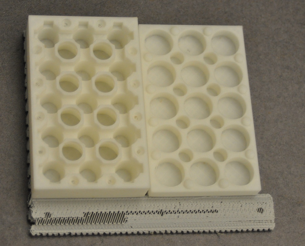
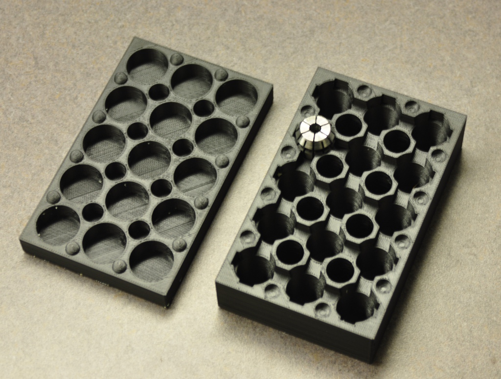
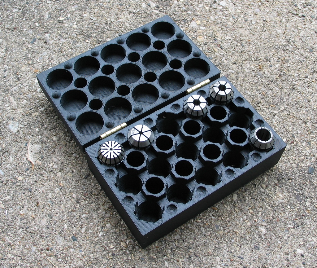
Of course, the obvious solution is to make something myself. A simple tray with appropriately sized holes would be functional enough, but I wanted something with just a little more elegance. While some of my most treasured tools have wooden cases, I have no problems with a good plastic case (and have on at least one occasion purchased a really crummy tool for no other purpose than for the halfway decent plastic case that it comes in).  So I whipped up a box in SolidWorks that could contain 15 ER16 collets with a matching lid.  I added some bumps around the outside edge between the halves to key them together so the lid would stay in place, and then sent it off to the printer.  The result was the box mentioned in this post from a few months ago. It wasn’t a great quality print as mentioned in the post, and I had incorrectly estimated the sizing of the cutouts for the collets which left them sticking up too far to let the lid close fully.

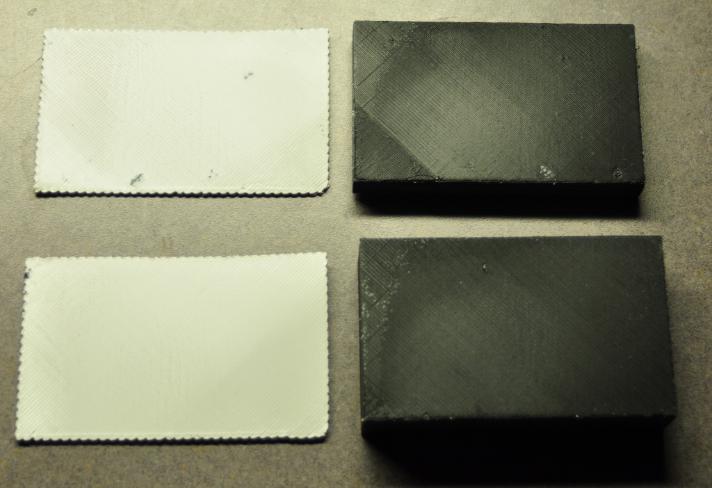
I gave it another try with a fixed model in Insight with the black Bolson ABS material, and things fared much better.  The interface between the support and model material wasn’t great, but I quickly discovered part of the problem:

The lid (upper right) has a darker triangular patch on the bottom left corner.  This is because no material was deposited there on the first model layer – there was so much ooze from the model material that a good deal of it flowed out during the lengthy build of the support layers.  As the machine was trying to print the perimeters of the first layer and the start of the infill on the lid, no material was coming out since the liquifier wasn’t full. Thankfully, this can actually be accounted for in Insight, as you can instruct the printer to purge material for longer than normal in order to top off the liquifier – I’ll need to remember to do this on builds with lots of base layer surface area.

No matter – collets fit this version just fine, and I’m not terribly concerned about aesthetics on something that’s going to get knocked around in the garage.

My original plan was to build hinges into the model – I wanted to have lugs coming off the back of the base and lid with circular recesses into which small disc magnets would be glued.  The magnets would attract each other and act as a hinge axis while hopefully providing enough friction to keep the lid open even when at an angle.  I’d still like to explore that concept in the future, but to finish this project in a hurry I simply used a pair of small hinges from Lowe’s.  I now have all my collets in one place next to the Taig in easy reach, and was pleased enough with how it turned out that I uploaded the design to Thingiverse. Much to my delight, it was chosen as a featured item!

Quick CNC work

I’m always impressed by Frankie’s ability to machine one-off parts on his Taig with minimal time spent on generating the toolpaths, which is something that I want to become better at. I’ll frequently over-think and puzzle over the CAM side so much that I wind up just bashing out parts manually on the Tree. However, […]

I’m always impressed by Frankie’s ability to machine one-off parts on his Taig with minimal time spent on generating the toolpaths, which is something that I want to become better at. I’ll frequently over-think and puzzle over the CAM side so much that I wind up just bashing out parts manually on the Tree. However, for a recent project I needed to do a lot of cutting in odd shapes that would be crazy to do manually for a single part, so I gritted my teeth and dove in.

As part of my growing RC aircraft addiction, I had purchased an Ikarus SU27-XXL kit as a fun ‘zoomy’ plane to advance beyond my trusty Slow Stick. My original plan was to use the brushed motor included with the kit – why discard a perfectly good motor, even though it may not be as powerful and efficient as a brushless one?  Well, a good reason is that brushed ESCs (electronic speed controller) are much more difficult to find these days than their brushless counterparts.  So I went brushless anyhow and purchased a motor and ESC.

Since the new 400 brushless was mounted at the base rather than the face, I couldn’t use the included light plywood motor mount.  I needed to build my own custom motor mount, and I happened to have some 3″x3″ squares of 1/16″ G-10 fiberglass sheet left over from a project that would make for very sturdy construction.  I drew up the needed parts in Cadkey and then tinkered with GibbsCAM at work to hopefully output usable toolpaths.  Fortunately, I’ve gotten much better in this regard, and the G-code worked out just fine.

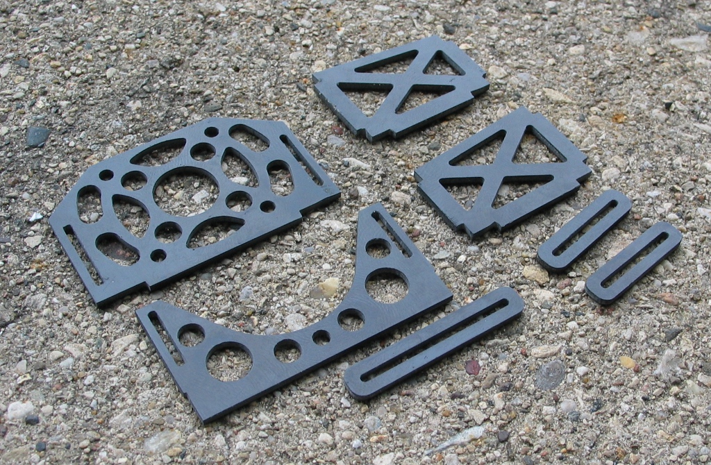
I used a hunk of scrap polycarbonate bolted to the tooling plate on my Taig as a sacrificial base.  Frankie recommended using carpet tape to hold sheet stock flat for machining, and it worked like a charm.  I’m using a 1/32″ carbide cutter to do the milling – I think it cut through the sheet in 3 or 4 passes.  When done, the parts were easily pulled off of the base.

After removing the tape and adhesive with a ‘Goo Gone’ type of solvent, here’s the parts I had.  As it turned out, I could have skeletonized them far more than I did, and using 1/32″ G-10 may have been an even better material.  I did have to do a bit of filing by hand to make things fit – the original plywood parts were laser cut and so had perfect square cornered slots, which obviously can’t be done with a round endmill.

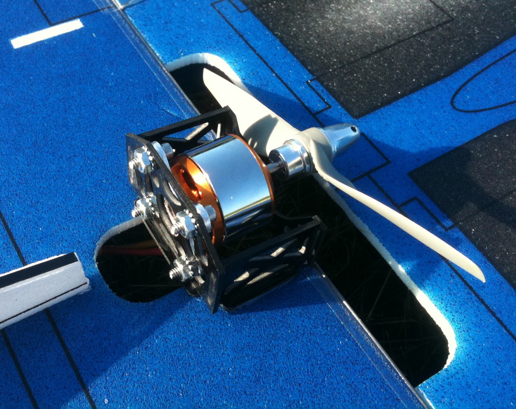
Glued together, it looks pretty good!

Fits beautifully on the plane and certainly looks like the beefiest part of the entire airframe.

Unfortunately, she would never look this good again…  On the final flight (just after I had moved up to a larger prop that finally provided the performance I wanted), I pulled out of a fast low level loop right into a tree, and the brittle Depron foam snapped all over.  The motor and mount tore free from the plane and was unscathed, however, so I’ll be dropping the unit into a scratchbuilt MiG-29 made out of pink sheet foam from the home improvement store.  I have a feeling that the motor mount will easily outlast that airframe as well…

Retro drilling

My interest in hand tools is generally rather limited.  While I admire (and am frequently awed by) the skill of artisans the likes of Roy Underhill (who is arguably the patron saint of human powered woodworking), I rarely find metalworking hand tools to be anything more than quaint when powered alternatives exist. There are exceptions, […]

My interest in hand tools is generally rather limited.  While I admire (and am frequently awed by) the skill of artisans the likes of Roy Underhill (who is arguably the patron saint of human powered woodworking), I rarely find metalworking hand tools to be anything more than quaint when powered alternatives exist. There are exceptions, of course – I still don’t have a bandsaw in the garage, as my hacksaw is far more space efficient and far less expensive (plus, I can bring my bar stock to work and use one of our large cutoff saws). Hand files are almost always more useful than a powered filer, etc. Drills, however, are another matter – you would have to be daft to want to use a hand drill rather than an electric drill. Or so I had thought.

Many years ago I purchased The Machinist’s Bedside Reader series from Guy Lautard. The third volume had a fascinating description of a very old (though at the time, still in production), very simple hand cranked drill. What made the device so interesting was that it was able to drill holes through almost anything thrown at it – steel armor plate, bearing raceways, high speed steel, even plate glass. By hand. The secret to the Cole Drill was a threaded collar below the crank arm that applied massive downward pressure.  “Low speed, high feed” in machining parlance.  Not only that, but the drill was designed in a very modular fashion – the column is nothing more than a piece of pipe or solid rod, as the drill is generally intended to be bolted to whatever it is that you’re trying to make holes in.  Rather than taking your work to a drill press, you take the drill press to your work.  Granted, you can do the same with a portable electric drill, but the Cole has the advantages of rigidity, extreme feed pressure, no electricity needed, and won’t tear your arm off if the bit catches.

As mentioned, the Cole Drill was still being manufactured up until maybe 2005 or so by Cole Tool Mfg.  Despite being ‘old’ tech, they still commanded a rather hefty retail price (presumably limited demand led to the product being discontinued).  While the drills have been routinely available used on Ebay since that time, it seems that prices have been going up – I seem to recall the going price to be around $60 or so a few years back, but now it seems that getting one for under $100 is a bargain.  Admittedly, I have zero use for a Cole Drill.  However, given the ‘field expediency’ of such a tool (drilling holes in a truck frame miles away from a power source being a good example), it’s a tool that I’d really like to be able to put my hands on in a hurry should the need ever arise.

I finally found one on Ebay that wasn’t horribly expensive, owing to a fairly rusty look to it.  However, the seller said that the drill had been purchased new, had been barely used, and had been sitting in an Arizona workshop for the past 30 years or so.  There was a pretty good chance of it cleaning up very nicely, so I bought it.  When it arrived, I eagerly opened up the box to have a look.  ‘Stout’ would be the adjective at the top of the list when attempting to describe the unit.  It was a little larger than expected, and most certainly heavier.

I hosed it down with Gibbs spray (another product touted by Guy Lautard) and set it aside to soak in and and help remove some of the rust. After wiping it off, things looked a bit cleaner, and I took it along to metalworking class so that Frankie could make patterns from it and hopefully bang out a few castings.

Once I had the drill back in my hands, I printed out a few pieces of information from the web and gave them and the drill to my dad as a long-planned present.  Dad is one of the few people I know who has the mechanical ingenuity to use such a tool to its full potential, and will probably have far more opportunities to put it to good use than I ever will.  But at least I now know where I can borrow one in a hurry if I ever need it!

What a difference three thou makes

With the PP3DP filament having proven itself admirably in the Stratasys, I ran more parts with the material and set up a job consisting of a little box to hold ER-16 collets and a paintball gun trigger frame.  Since I don’t like to have the machine powered up and sitting idle at full temperature for […]

With the PP3DP filament having proven itself admirably in the Stratasys, I ran more parts with the material and set up a job consisting of a little box to hold ER-16 collets and a paintball gun trigger frame.  Since I don’t like to have the machine powered up and sitting idle at full temperature for long periods (thereby cooking the filament), I try to adjust the parameters so that the job will complete during the day, allowing me to immediately start up a new job, or power down the machine.  There’s a few methods that I use for this – I can add or remove parts from the job, I can adjust the infill density (turning on the crosshatch options for a faster ‘sparse’ infill), or I can change the layer thickness (thinner layers give more precise parts but take longer).  For this particular job, I wanted to use a sparse infill to conserve material, and wound up changing the layer thickness to 0.007″ down from the normal 0.010″.

This adjustment of the layer thickness also affects the base layers (‘raft’ in RepRap speak), and since the foam build base I currently have in the machine is getting a bit ratty, I increased the number of base layers from the normal 5 to 10 for a total base height of 0.070″ to traverse the increasingly rough terrain of the foam (I have a box full of new foam bases – I should just replace the darn thing).  While I had run 0.007″ layers with the PA-747 and MG47 materials, I had never done so with support material.  I watched the base layers progress to see how well they’d form with a smaller slice height.

Blurry photo - I have 'new camera syndrome' (also known as 'still trying to figure out what all these buttons do')

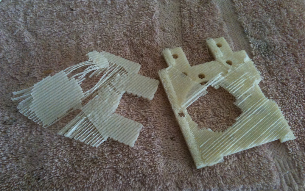
On the right side of the base, you can see a bit of waviness on some of the roads in the center.  As the nozzle would make a pass, the ‘wall’ that was being formed would flop slightly to the side – the long straight lines of the roads didn’t help the wall stiffness any.  As the freshly deposited topmost road cooled and contracted, the wall would return mostly to normal shape, but some waviness remained.  On the left side, the top layer of the base is being laid down, and the support material actually started ‘bunching up’ in spots, resulting in a raised, rough surface.  I knew this would probably cause the model to become too infused with the support to allow the two to separate easily, but I let it run anyhow.

Poor adhesion between the model and base

When complete, I had significant warping and lifting on the corners of the trigger frame part, though support for holes and overhangs worked beautifully.  The poor adhesion to the base could be due to the concave surface on that face of the part – rather than having a solid face, the support layers under the trigger frame are an open crosshatch, so there’s not as much contact area.  The box halves fared better, though I had highly variable adhesion to the base layer (rotten at corners, yet fused together where I had roughness on the base layer).

Although I hadn’t run the MG47 with support, I wondered if the lower die swell of the MG47 helped provide such good results when running at a 0.007″ slice height.  I realized that I had never checked the die swell of the P400S support material, so I finally checked it – a whopping 0.020″!  It makes sense that the support material wouldn’t act as kindly with such a small layer height – it wants to swell up, as it’s being ‘smeared’ to a road width much greater than the road thickness.

At this point I wondered if newer algorithms and flow curves present in Insight might make 7 thou base layers behave a little better.  Unfortunately, Insight never had support for the 1600 (and official support for the entire FDM thousand series machines was dropped at the end of the version 6 lifespan), though it can generate output for the 1650.  Given that there are a number of 1650s still in use, yet I’m the only one I know of with a 1600, it was possible that differences between the two are minimal.  In looking through generated output from QuickSlice for the two models, it looked like parameters were very similar (though the 1650 is run a little faster).  I crossed my fingers, set up Insight to send to a 1650 and let it rip on a Mendel test part at a 0.010″ slice height.  Wonder of wonders, it ran without a hitch – a part that would take an hour in Quickslice would take only about 45 minutes through Insight!  I set up a whole plate of Mendel parts, and it ran equally well.  I then tried a small part at a 0.007″ slice height in Insight – it ran fine, so perhaps having a large surface area for the base is an issue.  Insight also has several support styles available, so I’ll need to play with those settings as well.

A challenger appears!

With some other projects having consumed my attentions for the past few weeks, I was eager to return to more Stratasys experiments.  Having acquired enough breakaway support material to last me for the foreseeable future, I could once again be running with both extruders operational.  One material that I’ve wanted to try for quite a […]

With some other projects having consumed my attentions for the past few weeks, I was eager to return to more Stratasys experiments.  Having acquired enough breakaway support material to last me for the foreseeable future, I could once again be running with both extruders operational.  One material that I’ve wanted to try for quite a while is the 0.070″ ABS filament used on the PP3DP UP! printer, as people had mentioned that it was a bit different from the Chi Mei PA-747 ABS filament sold by Makerbot, New Image Plastics, Village Plastics and most other US suppliers. The problem is that overseas ordering is rather a pain – while PP3DP does now take Paypal, they still need a minimum order of over $100 (and stick the buyer with the paypal fees as well).

Fortunately, UP! user Enrique Muyshondt set up desktopFab to act as a US dealer for PP3DP printers and supplies. I ordered a 700 gram spool (1.54 lbs.) for $35 plus $12.34 shipping. Unfortunately, Enrique has since had to increase the price to $40 per spool – it seems PP3DP really doesn’t have any sort of dealer margin built into their price structure.

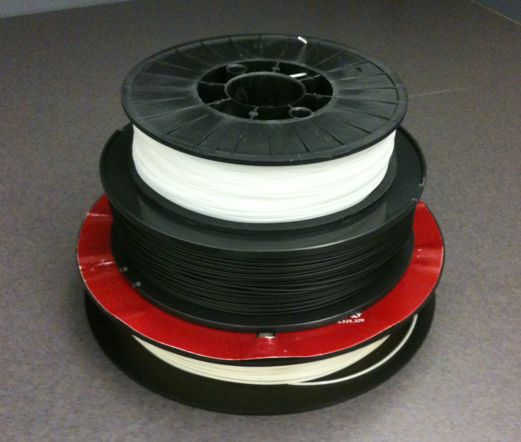
A Stratasys 2lb. spool on the bottom, a Bolson 2lb. spool in the middle, and a PP3DP 1.5lb. spool on top.
The spools are pretty small, but then again, the UP! printer that they’re intended for use with is a small desktop printer.  Happily, they have a 2″ mounting hole, so FDM users don’t have to re-spool onto empty Stratasys reels.  I threaded the material through the FDM 1600 and after waiting for the head to come up to temperature, I loaded it through the T12 modeling tip.  The extruded material looked and acted just like Stratasys P400, so I grabbed a micrometer and checked the die swell – 0.0175″!  Time to get the support material loaded and try making some parts – this was very promising.  Despite being honest-to-goodness Stratasys breakaway support material, I had trouble with it kinking between the feed wheels and the liquifier inlet.  I had almost resigned myself to tracking down some Vespel rod (horrifically expensive) to machine a new inlet that would reduce the distance to the drive wheels when I figured I’d try drilling out the nozzle again with a 0.011″ bit.  There must have been some buildup in the tip, as I had no more jamming after running the drill bit through.

I thought I'd give Adrian's cute little mini-extruder a try.

I could post lots of pictures of all the results, but I’ll keep it brief and simply say that the PP3DP filament runs great.  If I didn’t know any better, I’d swear that it was Stratasys P400 – it has the same matte finish, die swell, adhesion to support material, etc. that the OEM filament has.  It does seem to have a substantial amount of ooze, though it has been rather humid lately and I didn’t bother trying to dry the filament (it came in a sealed bag with desiccant).  While I’ll certainly continue with investigating alternate materials (the MG94 should be extruded soon), the PP3DP filament is easily the best bang-for-the-buck model material for Stratasys owners at this time.  However, one possible caveat is quality control – several months back, a number of UP! users noted that a batch of filament put out noxious fumes when run. While this isn’t much of a concern with a closed oven type of machine like a Stratasys, it may indicate that batch-to-batch consistency has yet to be perfected by PP3DP’s filament source.  Still, this is nitpicking about second-hand information – when I run out of the PP3DP filament, I’ll have no qualms about ordering more.

More build surfaces that don’t work

Since I’m pretty much out of support material for the Stratasys (well, not really, but I hate to break open my very last reel of OEM P400 support), and my extruder hasn’t yet run the HIPS that I hope will be a suitable substitute, I’ve been playing with alternative bases for building. When I first […]

Since I’m pretty much out of support material for the Stratasys (well, not really, but I hate to break open my very last reel of OEM P400 support), and my extruder hasn’t yet run the HIPS that I hope will be a suitable substitute, I’ve been playing with alternative bases for building.

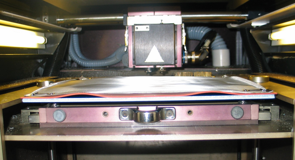
When I first started making the build platform, one of the surface materials I ordered was a very fine stainless wire mesh. My thinking was that it would provide enough surface roughness to mechanically bond with the ABS, but could be peeled off after cooling. I placed the wire mesh over the silicone sheet I had originally tried using and clipped it to the Garolite platform.

The mesh didn’t lay perfectly flat, but it seemed like it should be okay.

However, after coming up to temperature, the silicone sheet under the mesh expanded and buckled.

I tried running a part outline anyway, but the flex of the mesh prevented a good bond between it and the ABS in most places.  Some spots did have decent adhesion, but given the flexibility of the mesh, warping and curling would undoubtedly remain a problem even if I had decent adhesion all around.

The next idea came to me after seeing that Makerbot started offering PVA 3mm filament. Given that PVA has such a low melting point (and that the material is highly hygroscopic), I’m skeptical that it would be a good support material for ABS, but it did give me an idea. I recalled that PVA is commonly used as a water-soluble release agent when molding fiberglass. What would happen if I put down a base of MG47 ABS, brushed on PVA as a release, let it dry, and continue building the ABS part?

I used a Mendel part and modified the Quickslice parameters so that it would create the base layers using model material rather than support material.  Annoyingly, there appears to be a bug in Quickslice 6.4 that results in a single layer of support material being laid down regardless of if you tell it to use the other tip!  Thankfully I still had enough adhesion between the second layer (first deposit of ABS) and the foam base to keep it stuck down reasonably well.

I added a ;PS command to the generated .SML file so that the machine would halt after creating the base, and then used a sponge brush to brush on a few coats of PVA.  I noticed some crackling sounds from the ABS/foam bond when brushing, but didn’t think much of it at the time.

I put the PVA coated base back in the machine, let it dry for about 15 minutes, and hit the pause button to let it continue with the build.  I noticed that the model tip seemed to be trenching through the PVA layer, but let it continue onward.

D’oh!  When I checked back later, I realized I hadn’t seated the tray carrier fully to the rear during the base build, and the model was hanging off the front edge.  This was far enough into the build to see if the PVA would serve as a good release, so I halted operation and pulled out the tray.

I was able to peel up the two ‘tabs’ on the base a little to separate them from the part, but the rest of it (as indicated by the green area where there is still PVA) wasn’t going anywhere.  Time to let the piece soak in water overnight to remove the PVA.

Well, the results were not as good as hoped.  Despite the PVA layer, the model ABS bonded quite well to the base ABS, and clean separation of the two wasn’t really possible.  Well, what if I tried increasing the distance between the base and model?  Between each layer in the .SML file, there is a relative move upwards in the Z-axis, followed by a relative move downwards in Z.  I modified the move between the base and model in the .SML file to provide 0.002″ of gap in addition to the pause needed for me to brush on the PVA.

I went through multiple iterations of this, with warp/lifting of the model layers always happening, even as I decreased the gap between the base and model and reduced the amount of PVA applied.  Finally, I was running with no gap and realized that thermal stress during the first run must have raised up the base slightly causing the model roads to plow through the PVA and bond to the top base layer.

As it turned out, I later found that Dr. Adrian Bowyer (founder of the RepRap project) had investigated this concept nearly 6 years ago.  Instead of PVA, he had used plain old kitchen pantry corn oil, with reasonable success.  Of course, his build size was not as large as what I was attempting.  The idea probably still has merit (I’m curious about using acrylic spray paint as a release layer), but there’s plenty of other things to investigate…

I finally got around to opening up the bag of 4043D PLA from MakerGear to see if it might serve as a good support material. iFeel Beta has had promising results with this, so hopefully it would run on the Stratasys.  The material is certainly the most brittle filament I’ve tested so far, and I had a number of breaks when trying to wind it on a spool.  As such, I decided it was best to try feeding it through the rollers alone to see if it would break.

Fortunately, it fed fine through the rollers with no breakage, so I put the drive block back onto the head and tried pushing the filament through the liquifier.

This resulted in the highest feed torque values I had yet seen – this was not an easy feeding material.

Sure enough, the material eventually jammed as the toothed drive roller stripped into the filament, losing traction.

Still, running the material through a Stratasys is indeed possible – another user with a Prodigy Plus has done so successfully, and sent me this photo of the drive assembly.  The idler wheel is solid metal, unlike the one on my 1600, which has a urethane center section.  Machining such an idler may be a future project, but for now I’ll abandon the work with 4043D PLA.

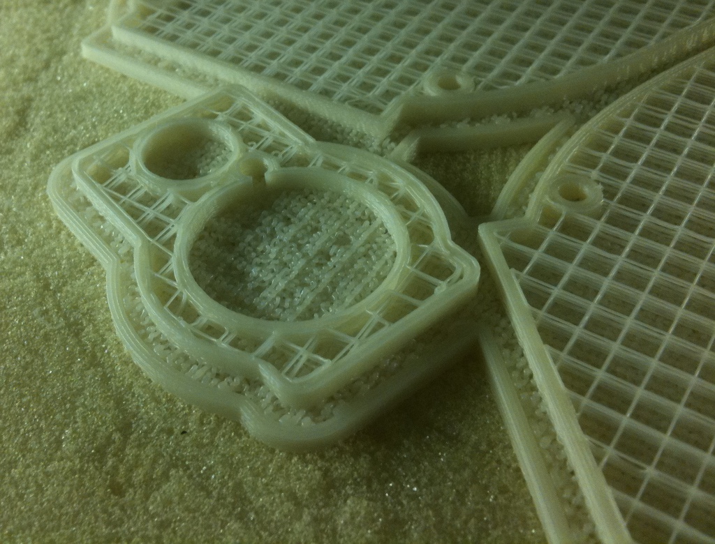
I decided to try using ABS as a base material and simply saw the parts off the base as needed.  As such, I manually added a base in Solidworks rather than adding a base (and faking the material) in QuickSlice.  I dotted the base with holes to make Quickslice generate perimeter roads to provide a little additional support, and then ran the part.

After the base was mostly complete, I halted the build, as there was a lot of sinking on the surface since the crosshatch infill had too large of a road width for the limited die swell of the MG47.  I recreated the base on the part, as the big 3/8″ thickness was definitely overkill, and it extended much further outward than needed.  With a reduced crosshatch road width of 0.0132″, I tried the part again.

The carpet-like top of the base layer reminded me that I had neglected to adjust the road width for the other layer types as well, but as the crosshatch infill was looking great, I let the build run until completion.  I also dropped the nozzle temperature down to only 240° C, as the feed torque wasn’t very high, and lower temperatures would droop less.

At the end, I had prototype paintball hopper halves and a pump for my Phantom paintball gun.  As noted, I had drooping filaments due to not having adjusted all of the road widths.

I expected a bit of drooping on the overhangs, as I wasn’t using any supports.

Rather than having to cut and sand the parts off of the base, they were able to be peeled away without too much fuss.  The crosshatch infill came out great, with no drooping all the way through the part.  I had intended to just tear out this infill, leaving the hollow shell, but the filament is a lot tougher than I had expected.

The base did lift from the foam base on one side, unfortunately, which let the hopper halves warp a bit.  With this build complete, I went back to QuickSlice to adjust the road widths for the other layers and tried running a small test part that used aligned roads as the top of the base.

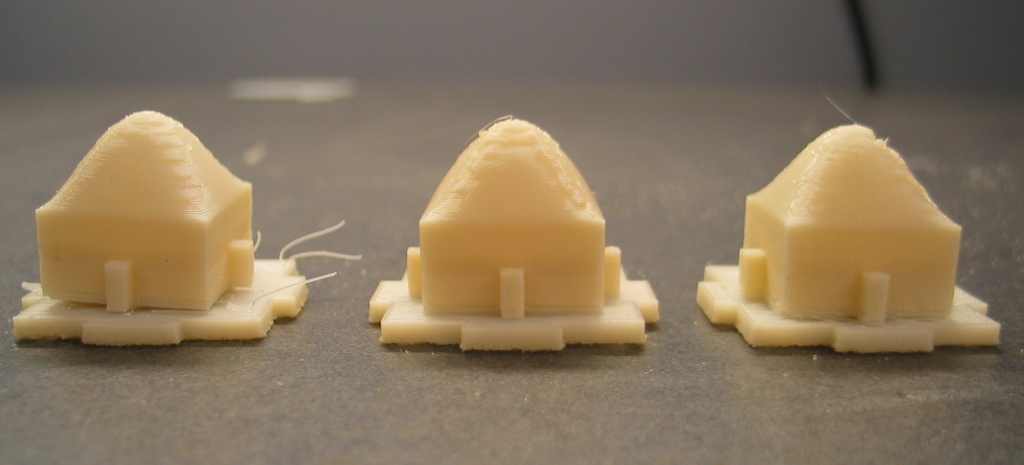
While the dome on the part didn’t come out perfect, I didn’t have the same sagging as before.  The stubs on each side were John Branlund’s idea as a way to check for backlash. Fortunately, I had no discernible backlash in the system.

The part separated quite nicely from the base – only minimal sanding would be needed to remove the traces of support from the bottom of the part.

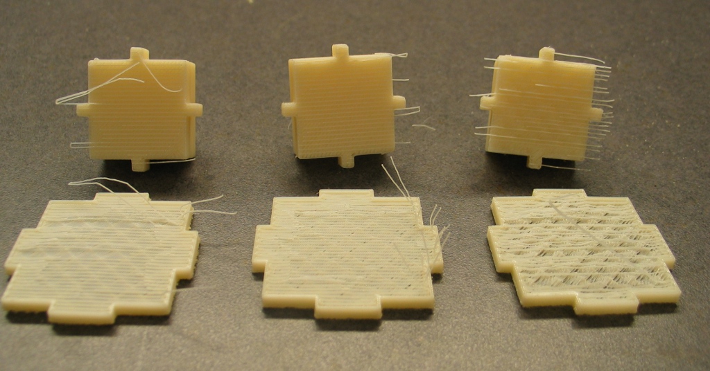
I ran 2 more parts at increasingly higher temperatures (left was 240° C, center was 255° C, right was 270° C) to see what the results would be.  Sagging on the top aligned roads of the base increased as the temperature went up.

Separating the part from the base also became more difficult with the increase in temperature, as the layer bonding became stronger.

Fortunately, more OEM support material has now arrived, so I can finally be back to proper operation shortly.