Gunsmithing without a 3D printer 1

Last fall, my friend Max helped his mom pick out a shotgun for home defense.  Being a fairly small lady, she took a liking to a youth model 20ga. Mossberg 500 and had a great time with it at the range.  However, the 22″ barrel that came with it was a little long for a […]

Last fall, my friend Max helped his mom pick out a shotgun for home defense.  Being a fairly small lady, she took a liking to a youth model 20ga. Mossberg 500 and had a great time with it at the range.  However, the 22″ barrel that came with it was a little long for a home defense gun, and I was asked if I might be able to chop it down to the legal limit of 18″ (in the US, a shotgun with a barrel of less than 18″ is considered a short barrel shotgun, and is subject to NFA restrictions).  The small amount of gunsmithing that I’ve done has always been for myself, but I was happy to take a stab at the project (worst case, I’d just have to buy a new barrel to replace the screwed up one).  Additionally, I needed to attach a rail-mounted Streamlight flashlight to the shotgun (that has no rails).  Sounded like a fun challenge, so I ordered some odds-and-ends from Brownell’s in preparation for the task.

The first step would be to start hacking away on the barrel.  Since the barrel has a vented sight rib, you can’t just use a pipe cutter to cut the end off (besides, I never liked the thought of that method anyhow – it would leave a nasty burr on the inside, and is rather a crude approach when you have access to machine tools).  Also, 18″ is right through the front edge of a rib, and erring on the side of caution is highly recommended – I would have to trim the rail back to the rib and leave a bit of barrel sticking out underneath that to make sure I’m on the legal side of 18 inches.

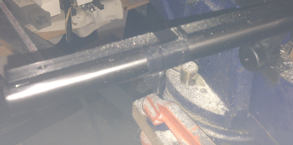
I clamped the barrel in a padded vise and proceeded to use a number of wraps of electrical tape through the cut area – protecting the existing finish is paramount.  I’m a garage gunsmith, but I don’t want my work to look like it was done by a garage gunsmith – I’d like the result to be something I can personally be proud of, so I took extra caution to prevent errant nicks and dings.  I should also apologize for the horrendous pictures here – I left the protective plastic sheet in place on my phone, hoping it would help protect the lens (which it does, but when the LED ‘flash’ turns on, it illuminates the sheet and ruins the photo).

Measure twice, cut once.  Or in this case, measure at least half a dozen times – anything under 18″ isn’t an ‘oops’, it’s a federal crime (if you don’t have an approved Form 1 for the shotgun).

I cut through the rib with a cutoff disc in a Dremel and stopped before I hit the barrel.

Then I lopped off the end of the barrel with a hacksaw.

Next was to clean up the front of the sight rail and end rib.  I taped the heck out of the barrel stub end and then used a flat file to smooth out the end of the rail and give the corners just a little radius so they wouldn’t catch on anything.

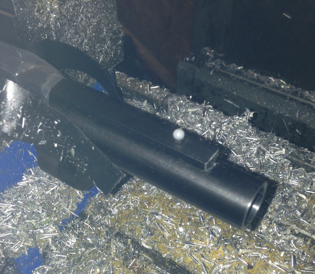
I used some vinyl drawer liner material with double-sided tape to line the lathe chuck jaws.

With the barrel inside a plastic bag to help keep it protected, I took light facing cuts across the muzzle until all evidence of hacksaw-ery was eliminated.  Then I used a small piece of sandpaper to knock down the sharp inside and outside edges.

Since the barrel shortening had removed the front bead sight, I needed to drill and tap further back on the sight rail to remount the bead.  I clamped the barrel in the mill vise and eyeballed it to make the sight rail level.  I then used an edge finder to indicate in the sight rail so I could be sure of drilling right on its center.

I drilled just behind the front rib and carefully tapped it out with a 5-40 tap.  That was all for machining on the barrel itself – the bare steel simply needed bluing.  Unfortunately, I don’t have any photos of this, as I was trying to simply do the job correctly rather than documenting it.  However, my general approach was to first thoroughly degrease the surfaces to be blued (the end of the barrel and the front of the sight rail and rib).  I wiped them down with rubbing alcohol and started a pot of water boiling on the stove.  I would dip the end of the barrel into the boiling water for a little while to heat it up, then pull out the barrel, shake off any water droplets, and quickly apply Brownell’s Oxpho-Blue Creme to the bare steel areas with a cotton swab.  After letting the solution blue the metal for 30 seconds or so, I wiped it off and dunked the barrel end back in the boiling water to clean off the solution and re-heat the metal.  I repeated this perhaps 8-10 times.  When everything was done, I washed off the barrel end once more, wiped it off, and applied some Remington gun oil to the newly-blued areas to keep them protected.  I think the end result was perhaps a touch lighter than the factory finish, but it’s hard to tell, and might just be due to the machined/filed surfaces rather than being factory polished.  At any rate, it looked good.

Now, how to mount that pesky flashlight?  Originally Max and I were thinking of drilling and tapping the magazine tube (the tube under the barrel where the shotshells reside) for Picatinny rails.  While this might work, I’d have to figure out how to align the magazine tube properly in the mill vise, and I’d have to contend with what would likely be a thin wall on the magazine tube (and interfering with the feeding action would be a very bad idea).  I then figured that attaching a rail via scope rings would be the best method – not only would I not have to drill through the magazine tube, but the user could adjust the flashlight position though a full 180 degree arc.  I purchased a sight rail with scope rings, as I had a crazy idea – mount the rings to the magazine tube and flip the rail inside-out…  The rail needed a bit of machining – I had to add extra slots (for the cross-pin on the flashlight to lock into), and I needed to machine the rail’s underside on each end so that the scope rings could clamp onto it from underneath.  With all of that complete (forgot to take photos, sorry), I had to adapt the 1″ scope rings to the 7/8″ magazine tube.

I used some scrap 1″ OD tubing that had a 3/4″ ID, and bored out the interior to 7/8″.  I then sliced off two rings with a parting tool.

I clamped each ring in the mill vise and lowered the quill so that the slitting saw sat on the top of the ring.  Then I raised the knee up by half the outside diameter of the ring plus half the thickness of the slitting saw’s kerf.  Slotting each ring allows them to collapse slightly and grip the magazine tube when each scope ring is tightened.

The mounting system worked perfectly, and the flashlight was easily attached.

The resulting platform turned out great, and she’s very happy with it – that’s all I could ask for!

Nerdy Derby

In August, Pete posted an innocuous message to the Milwaukee Makerspace mailing list: Now that Power Wheels is (mostly) over, we should turn our attention to this: http://www.nerdyderby.com/ I mean, we’d need space to do such a thing, but I think it would be awesomely cool. Who’s in?? Hmmm…  A ‘no rules’ pinewood derby?  I […]

In August, Pete posted an innocuous message to the Milwaukee Makerspace mailing list:

Now that Power Wheels is (mostly) over, we should turn our attention to this:
http://www.nerdyderby.com/
I mean, we'd need space to do such a thing, but I think it would be awesomely cool.
Who's in??

Hmmm…  A ‘no rules’ pinewood derby?  I was never in Boy Scouts, but racing cars certainly was appealing to any boy (and I raced many many Hot Wheels cars in my youth, with extravagantly banked and looped tracks, often borrowing construction elements from Lincoln Logs, Legos, Tinkertoys, and whatever else was at hand).  What better way to relive my childhood than to downhill race blocks of wood in the same fashion as I did with Hot Wheel cars with friends and cousins: without any rules.

Discussion on the mailing list quickly dove into the underlying physics, and how heavier cars will lose less of their overall potential energy to friction, which led many people to work on designs maximizing mass (and then resulted in questions on how to do lead casting – the competition was serious for the event).  My own thoughts were originally along this line as well, thinking of building a car out of steel plate with rails to keep it on the track.  But then I figured that just adding power to the car was really the best solution – the heaviest derby car still has only gravity to propel it, and a lightweight (though powered car) should certainly be able to best it.

Powering the wheels was the obvious method, but I had never messed with RC cars, slot cars, or any other powered car toys enough to know what sort of motor/transmission system they used.  The closest I had come was years ago when helping someone with concepts for a mousetrap racer.  My idea was to have a foam cone on the drive axle around which the string from the driving arm would be wrapped.  The string would first pull from the large end of the cone to maximize the torque and get off the starting line faster, and as the string unwound, it would be on successively smaller diameters to decrease torque and increase speed.  But how to determine the best shape for the cone, and what would be the best power source?  Rubber bands?  Torsion springs?  And how to make sure that power isn’t engaged before the starting gate drops?

I quickly discarded that line of thinking in favor of just brute force – stick a model rocket motor on the back of the car.  Of course, that would probably run afoul of the one rule imposed in an otherwise ‘no rules’ race – don’t damage the track.  While I could argue that scorch marks are merely cosmetic, it probably wouldn’t fly with race officials, and the open flame indoors may not be a great idea.  Plus, how to trigger it only after the start gate?  Someone else on the mailing list linked to information on CO2 powered derby cars, which are most certainly fast, but any bit of off-center thrust gives them a bad tendency to leave the track.  Given that there is a hump right in the middle of the official Nerdy Derby track, it was very likely that such a car would become airborne.

I then recalled a novel race car I had read about as a kid – the Chaparral 2J.  What made it so interesting was that it was built as the opposite of a hovercraft, so that a blower unit would actually evacuate air from underneath the car, keeping it glued to the road surface even when at low speed (compare to a modern F1 car that can generate tremendous downforce via aerodynamics, but only as a function of its speed).  Of course, the Chaparral 2J was banned from competition very quickly – sounds like just the thing for a ‘no rules’ race.  What to use for a fan suction system, then?  Well, a ducted fan seemed a logical choice – I hadn’t yet used one in any of my RC planes, but this seemed like an excellent opportunity to experiment.  If I angled the ducted fan back on the car, I could use it for thrust as well as forcing it down on the track.  With a propulsion method in mind, I briefly turned my attention to the wheels.  It sounded like plain old off-the-shelf pinewood derby wheels were being used by most other builders, but I figured disc style wheels with ball bearings could only help.

With the basics in mind, it was time to start designing.  Charles and Frankie were also building cars, so we met up at Frankie’s studio a few weeks ago for a day of design, construction, and the bull session that invariably occurs whenever the 3 of us get together.  Frankie was already well underway constructing his belly tanker design, and Charles had some solid design concepts sketched out for his own car.  I had only the vaguest notion of what I wanted to achieve and a copy of SolidWorks – okay, time to get designing.  I started out with the track itself, and drew up a section about a foot long.  Wheels around 1.25″ diameter felt about right, and I roughed out a model of the EDF unit that I had in mind for the car.  Throwing them all together netted me a skeleton of the main components.
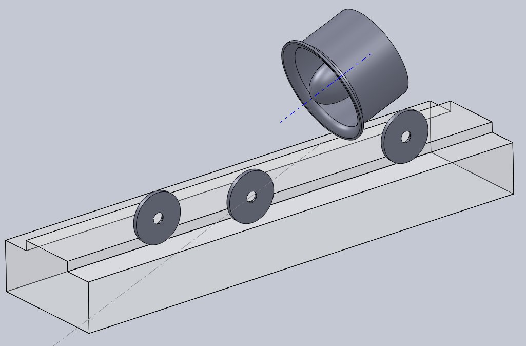
Given that the car’s stance was pretty narrow, I figured adding a set of outrigger wheels would be a good idea – just in case the car lost its footing due to the EDF’s torque.
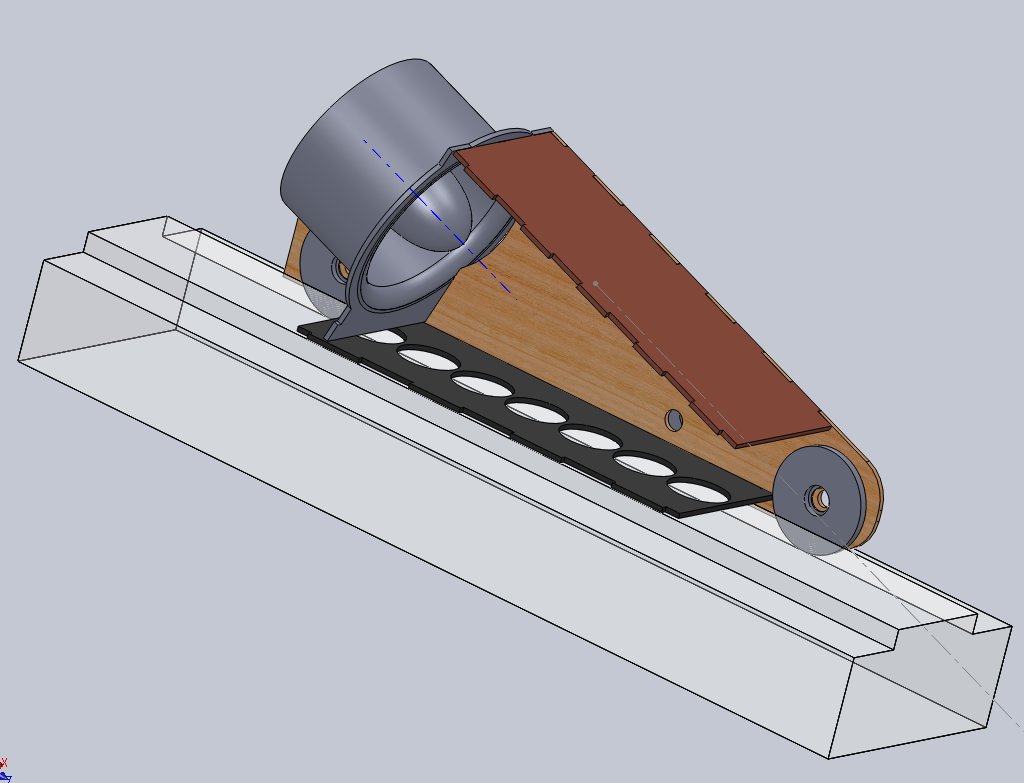
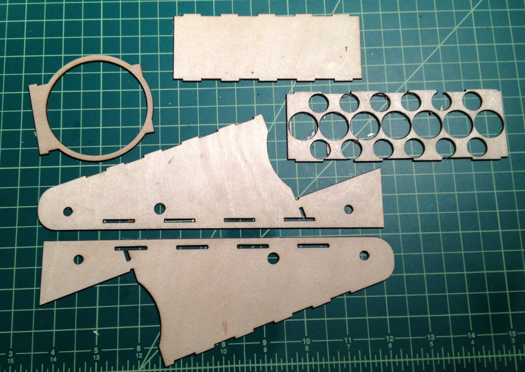
Most of the day was spent on hashing out the body itself.  What I originally envisioned was something sculpted, smoothly flowing and elegant yet powerful, like a Lola T70.  I may have fallen a bit short in that department.  I designed the parts to be laser cut out of 1/16″ plywood on one of the makerspace’s laser cutters, and figured that I’d somehow use 1/4″ aluminum tubing with 5mm fasteners for the axles (with appropriate flanged bearings pressed into the wheels).

I converted the models of the plywood pieces to be cut into DXF files and then arranged them together into a single panel that would span a 12″ wide piece of plywood.  The DXF for the sheet is here.  I stopped by the space on a Thursday night, but only the 25W laser was operational, and it was only able to be run at half power.  As it turned out, 12.5W was simply not enough – even after multiple passes, the poor little photons had managed to fling themselves no further than 1/3 of the way through the plywood.  I took the piece home, expecting that maybe I could cut the rest of the way through with a hobby knife and jeweler’s saw.

Fortunately, I didn’t have to resort to that, as a week later both lasers were fully functional, and Shane was just finishing up one of his nifty laser cut/engraved card boxes.  He helpfully assisted me with the finer points of the big 60W laser, and I was off and running.  Wow, what a difference!

Even through the protective window of the 60W unit, its vigor was unmistakable.  There was a little more charring than I would have liked, but I’m not about to complain – having it cut all the way through beats the heck out of cutting it by hand.  At home, I broke the pieces free.
Next step, I needed wheels.  I found a length of 1.25″ diameter plastic (some sort of phenolic, I can only assume), chucked it in the lathe, and started cutting.
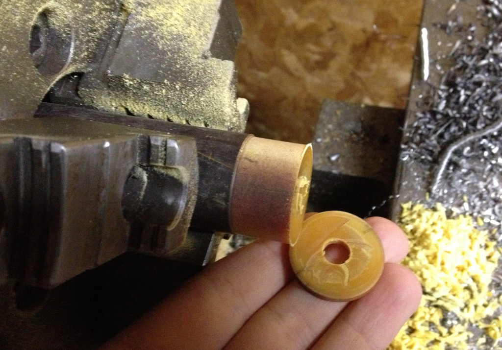
I drilled a hole in the stock before parting it off to provide (hopefully) a decent diameter to press-fit the flanged bearings into.  My parting tool has a bad tendency to drift to the left as I part off stock, so I needed a way to true up the wheels to be entirely flat on each side.  I figured I’d try machining an expanding arbor to hold the wheels, as it’s been rattling around in a tool drawer for years, awaiting a purpose.
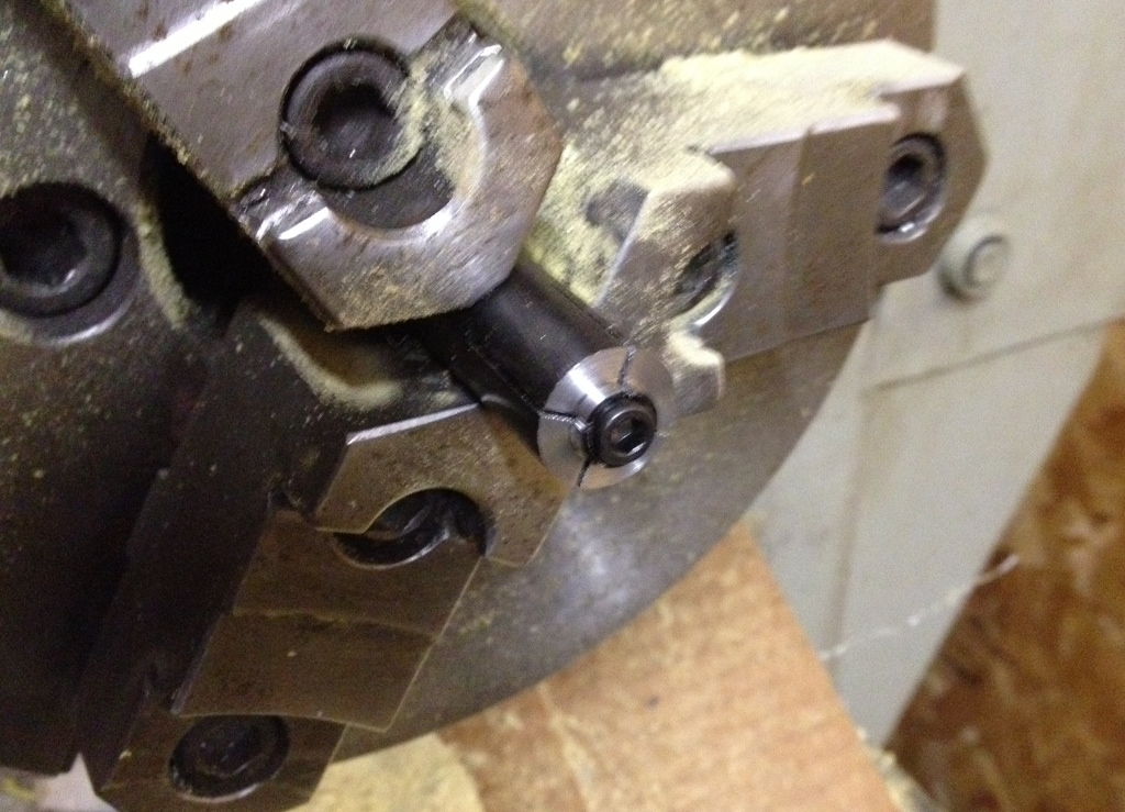
While it machined really nicely, it didn’t work out well in practice.  The plastic wheels still flexed quite a bit while being cut, and wanted to walk off the arbor as a result.  It was now getting down to the wire, and race day was approaching.  Scratch that – race day was here.  As of Saturday morning, I wasn’t sure if I’d be racing at all, but I’d certainly make a go of it.  After soldering bullet connectors onto the EDF unit, I was ready to glue together the shell of the car.

I used CA to bond the plywood together (having used copious amounts to seal/strengthen the parts themselves) and hot glue to mount the EDF unit.  While waiting for the CA to cure, I headed to the garage to do more work on the wheels.

Good old carpet tape worked well enough to machine the wheels to thickness – just go slow, take light cuts.
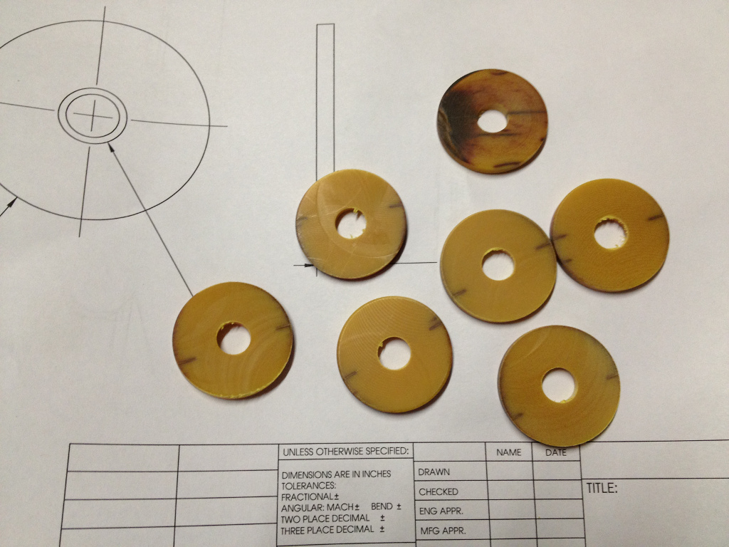
7 wheels (always make more than you need, because you just know you’ll mangle one during subsequent operations).  However, Friday had brought a potentially devastating bit of news – the raised center section of track was 1.65″ wide, and not the 1.5″ wide that I had designed to.  Much wailing and gnashing of teeth ensued.  Fortunately, I had designed the body after the wheels, and as such the wheels could actually be moved outside of the body with no ill effects. Realistically, this this even better, since having the wheels external would remove the need for outrigger wheels, and internal wiring wouldn’t have a chance to get tangled up in them.  Also fortunate was the fact that I am a horrific procrastinator, and since I hadn’t yet gotten to the stage of machining axles, I was free to modify my design as needed.
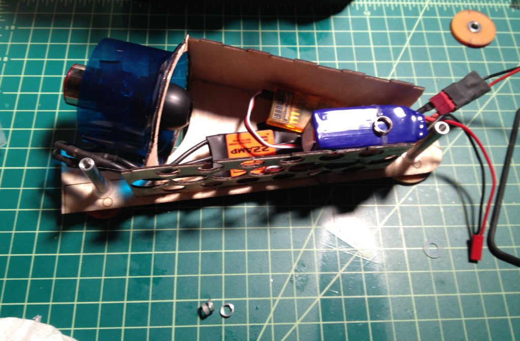
I drilled out some pieces of 1/4″ thick wall aluminum tubing and tapped the ends for 5mm threads.  I also cut some spacers so that the bearings wouldn’t run against anything else.  I then started packing the inside with components – a 22A ESC, a 2.4 GHz receiver, and an 800mAh LiPo battery (all credit to Charles for suggesting that I stick the battery inside – I had planned on running it externally for ease of access until he convinced me otherwise).  Ideally the ESC and battery should have been rated higher, but for burst use (under 3 seconds from start to finish), these components should hold up fine.  Besides, there’s always the ‘epic fail’ prize category should something go wrong.  Internal accessibility was not considered at all in the design phase, so the right body panel is held on by the axle spacers and wheels.

So 30 minutes before heading out the door to Bucketworks to attend the Derby, this is what I had.  A radio that I was using when attempting to fly my latest RC plane on it’s first and last airborne adventure (maybe I shouldn’t have transferred the ‘Centrino Inside’ and ‘Windows Vista’ stickers from my laptop to it), and a car held together with hot glue, CA, a few pieces of fiberglass fabric, and medical tape.  Perhaps MacGyver would be proud.  Or appalled.  Eh, whatever.  The car was assigned #32 as a race sticker, and I had a glance at the competition, which looked tough.

Pete’s ‘Raster Mobile’ certainly had mass, and Brant’s ‘Safety Car’ had lots of lights.
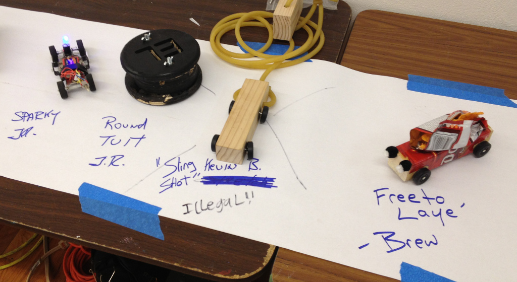
Fortunately, Kevin B’s “car” was deemed by race judges as illegal.  However, I admired his extension of the rules.  “Roads? Where we’re going, we don’t need… roads.” Brew’s Dorito-laden vehicle was a crowd-pleaser when it invariably ejected salted snack chips at the end of a run.  Unfortunately, Jim’s ‘Sparky’ was having electrical issues and wasn’t running nearly as fast as it had been on test runs.

Brent’s ‘Pootystang’ really had me worried.  A full diameter propeller will easily best a ducted fan unit in thrust, and he looked to be using the same battery as I was.

Ed’s “Aghghhhh!” was the best (only?) 3D printed car in the race.  [edit – Pete’s ‘Great White’ was also printed – forgot about that one!]

Charles finally gave his (highly polished after 5 hours of work) car a name of ‘2 ways’.  I added ‘both of them wrong’ to it (not shown in photo).  In the photo, it appears to be heading the right way (right to left).  He claims that the front end is actually the right side of the photo, for which he deserves to be mocked endlessly.   I think Rose entered ‘5 Rings’ and Dillon had entered ‘Indus’ (which was based on a pull-back racer).  Since we were to name our own vehicles, I decided to call mine “Waste of a Perfectly Good Afternoon” (that’s all that it was until that point).

Fortunately, I was paired against Charles for the first 2 heats.  He gave me a sporting chance by running his car in reverse – he keeps claiming that’s the front end “like a Studebaker”, but I know better.  I applied the throttle just enough to keep my car in the lead (seriously, I was worried about something erupting into sparks and flame – this was a 22A ESC with an EDF unit that can draw 33A).  This got me into the finals (thanks, Charles!  Sucker…).  I raced Jim’s ‘I Win’ and Brent’s ‘Sneaky Weasle’, which was amazingly fast.  Every time, I throttled up just enough to ensure that I was in the lead, but no more – damage to the car upon contacting the deceleration zone (a chunk of open cell foam at the end of the track) had me worried, as one race broke the EDF unit free of the body, necessitating emergency hot glue gun surgery.  In the end, I was in the lead at the final race, and gave it full thrust from start to finish to see just how quick it could go – 1.595 seconds was the elapsed time.  Incredibly, it survived intact!  After that, it was requested to see if the car could run the track in reverse and actually make it up the hill.  Our intrepid race official quoted Doc Brown’s famous words, the crowd gave a countdown, and I floored the throttle, easily sending it off the far end (thankfully Jim was there to catch it).  After that, there were the awards.

Frankie is out in Denver at the moment speaking at a conference, so this award certainly went to his belly tanker.

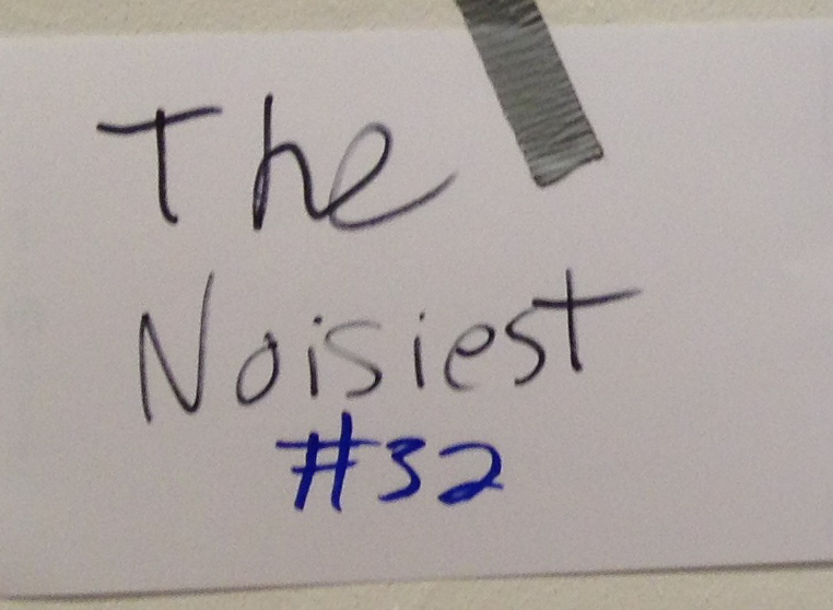
My car not only won as the ‘fastest’, but also captured ‘the noisiest’ and ‘best name’ awards.  No trophies or cash prize – just bragging rights.  As such, I’ve been telling attractive females that I’m a 3-time auto racing champion, but when they learn the details, they tend to edge away nervously.  *shrug*

http://wiki.milwaukeemakerspace.org/projects/nerdyderby

Gunsmithing with a 3D printer – Part 3

To say that the buzz generated around this project is heavy on “media hype” would be an understatement.  I could write a great deal on this alone, but I’ll content myself to refer people to David Chernicoff’s excellent article explaining why this is not a big deal and the apocalypse is not nigh.  Being at […]

To say that the buzz generated around this project is heavy on “media hype” would be an understatement.  I could write a great deal on this alone, but I’ll content myself to refer people to David Chernicoff’s excellent article explaining why this is not a big deal and the apocalypse is not nigh.  Being at the center of a story really lets one see how the media sausage is made, and I’m amazed at how much misinformation gets copied and introduced as a story gets picked up by a string of outlets.  It’s like a giant journalistic game of “telephone”.  The past few weeks have also seen a far bit of buzz on the Defense Distributed project, which aims to design a 100% 3D printable firearm.  It’s certainly an interesting engineering challenge, and one which I’ve pondered myself over the past year and a half.  The problem is that even the strongest 3D printable thermoplastic currently available for the FDM process (Ultem 9085) doesn’t even have half the tensile strength needed to withstand the 24000 psi maximum allowed chamber pressure of the .22LR round as defined by SAAMI.  As such, yes, a 100% 3D printed gun made on a RepRap could certainly go ‘bang’, but even with a barrel of large enough diameter to keep it from exploding, there would be so much deformation in the bore that most of the available energy would be sapped by gas leakage around the projectile (to say nothing of the utter lack of accuracy).  In the end, you’d have a smoking, charred crater left for a barrel bore after the single shot.  Quite an expensive proposition, given that such a gun would almost undoubtedly be classified as an AOW, requiring sign-off by a chief law enforcement officer, background check, submission of fingerprint cards, $200 for the tax stamp, and up to a 6 month wait for approval before you could commence printing one.  If you have an interest in hobbyist gunsmithing, make sure to familiarize yourself with the rules and regulations that your project would have to abide by – it’s not worth risking a paid vacation to ‘Club Fed’ to 3D print a ‘zip gun’ that could very well cause a great deal of injury to yourself and others.  Please stay safe and legal, everyone.
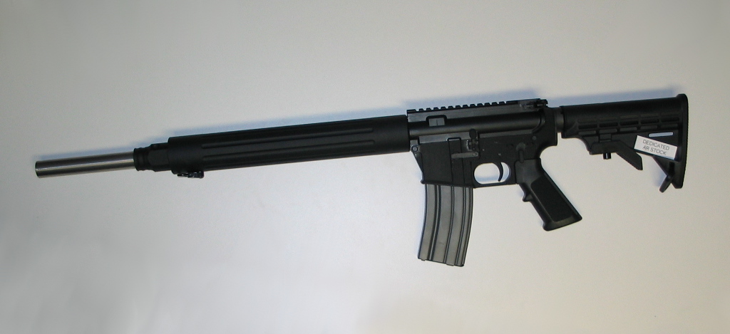
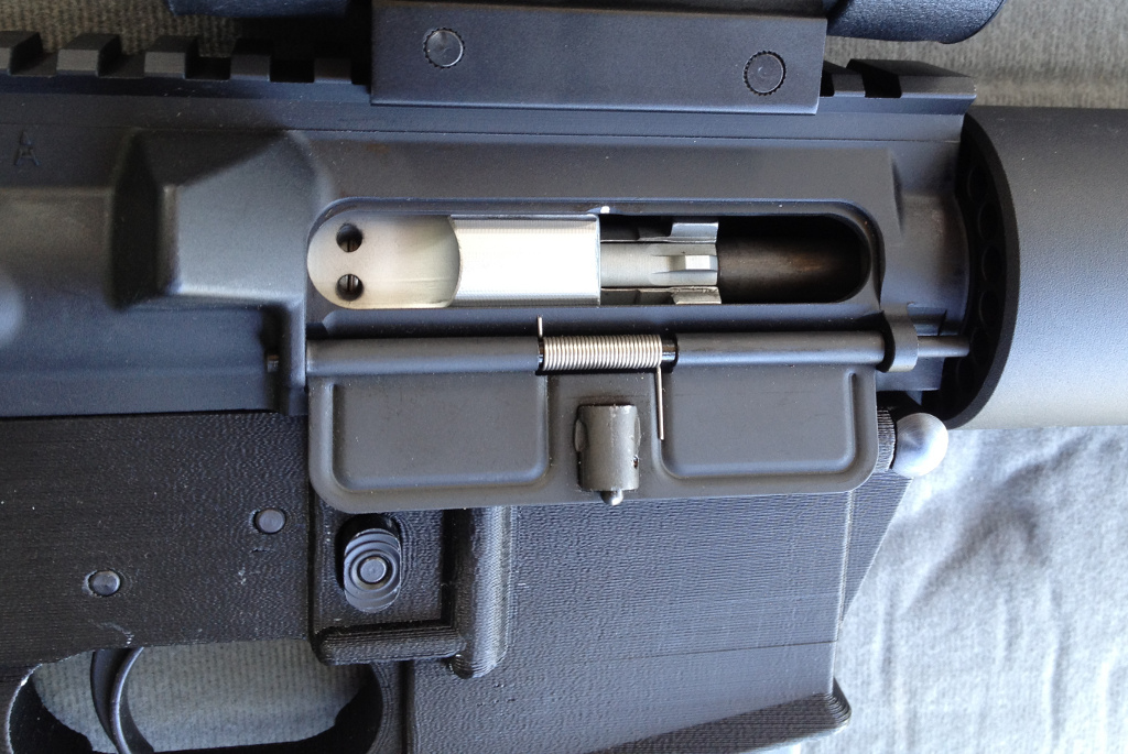
On a more interesting historical note, I found that my printed lower is not in fact the first 3D printed firearm to be tested (as per the GCA definition, where the receiver itself is legally a firearm).  Many people pointed me to the Magpul Masada, as the prototypes had SLS printed lowers and furniture.  However, the lower of the Masada is not the controlled part – it is in fact the upper receiver, which was machined aluminum on the prototypes.  No, the first tested 3D printed firearm as best I can tell was actually a silencer!  Yes, as per the definitions of the 1968 GCA, a silencer is by itself considered a firearm.  Admittedly, this starts splitting hairs, and there may very well be other examples of prior art – Magpul’s FMG-9 prototype was primarily built with SLS printed parts, but used a modified Glock 17 as the core, and I’m unsure of whether the receiver was Glock or SLS.  In fact, it may very well be that exactly what constitutes the receiver on the FMG-9 has yet to be decided – there has only been a single prototype made, and until the ATF’s Firearms Technology Branch is asked to determine which is the controlled part, it could be entirely unknown.  As well, firearms companies have been incredibly secretive about their usage of rapid prototyping (I’m still trying to track down specifics on the SLA silencer) – I imagine there’s some engineer out there saying “Boring!  I did this stuff like 10 years ago!” but can’t say a word due to non-disclosure agreements.

Anyhow, back to tinkering.  While the tests on the printed lower ran just fine with .22 ammunition, the real test would of course be the round that the AR-15 was designed for, the .223 Remington cartridge.  I re-assembled my original DPMS 20″ bull barrel upper and attached a collapsible stock to my printed lower.

Again, with a fair bit of trepidation (though tempered with an engineering background), I used only a single round to begin with, which functioned just fine.  A much louder report than .22LR to be sure, but I was pleasantly surprised by the utter lack of recoil – Eugene Stoner was a very sharp fellow, and despite my misgivings about a direct impingement system versus a piston based system, I’m impressed by how effectively his design works.  However, when adding more rounds to the magazine in testing, I had issues with extraction and feeding.

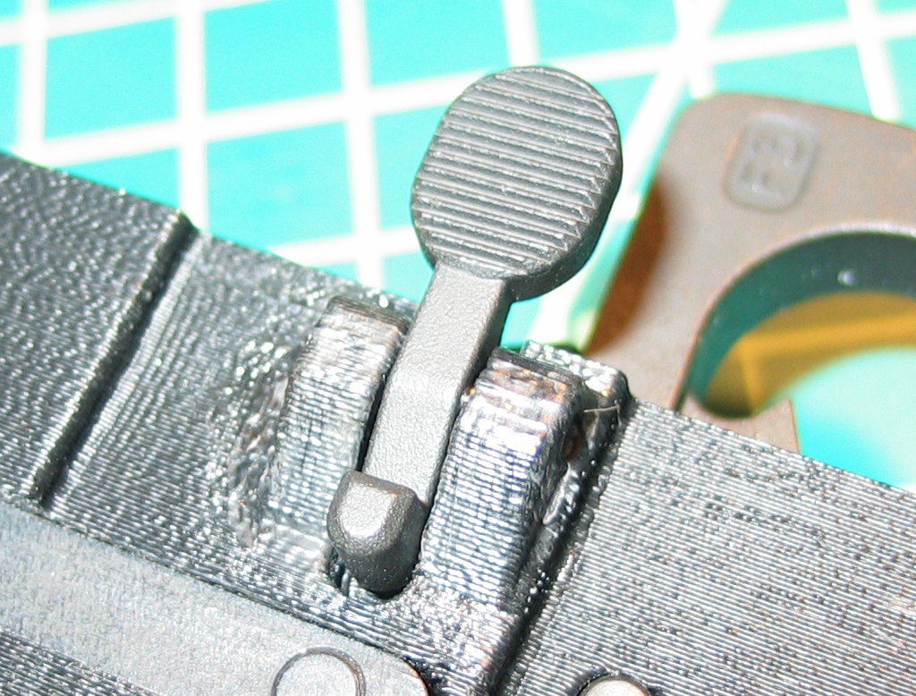
I switched out my printed lower for my aluminum lower and tried again.  To my chagrin, the problems persisted, so I stopped testing, wondering if perhaps the steel-cased ammo I was using could be to blame.  The fact that I still didn’t have a detent for the rear takedown pin was also bothering me, as it meant that I didn’t yet have a fully functioning 3D printed lower (and as things loosen up and wear in, the rear takedown pin tends to drop out onto the floor without the detent in place).  I purchased some 1/8″ OD brass tubing with an ID suitable for the detent spring from McMaster-Carr and set about machining an insert that would house the spring and detent.

I did have to drill out the front of the tube slightly, as the detent is a little larger in diameter than the spring itself.  I also tapped the rear of the tube for 4-40 threads so that a set screw would keep the spring in place without any need for an end plate (so the lower can be operated as a .22 pistol with absolutely nothing screwed into the buffer tower).

After drilling out the hole in the lower to 1/8″, I pressed in my machined detent tube (with set screw, spring and detent) with a dab of solvent to secure it in order to capture the tube in the lower receiver.  It would have been nice if Stoner would have made the lower receiver so that it didn’t require such work, but realistically, an AR-15 stock would rarely (if ever) need removal (in fact, proper assembly procedure is to stake the rear plate in place after the castle nut is tightened).

I then gave the upper a good cleaning and oiling – while it was still brand new, the fact that I had purchased it a good 6 years ago meant that it was extremely dry.  I also purchased some brass .223 ammunition, as some uppers just don’t like steel cased ammo, and I wanted to improve my chances as much as possible.  Testing with the brass cartridges and freshly cleaned upper yielded excellent results with the aluminum lower, with perfect cycling.  Swapping in my printed lower, however, brought the old feed and extraction issues right back.  So, what could be the issue?  My primary suspect is flex in the buffer tower.

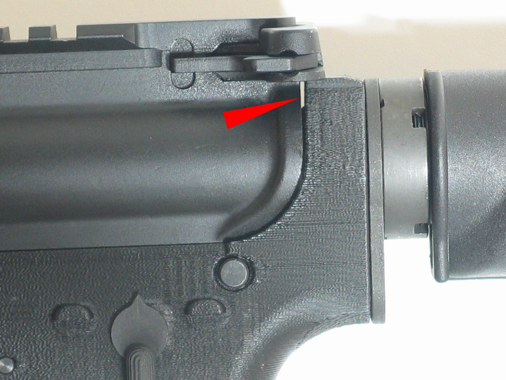
There is a small gap between the upper and lower, and this gap does indeed widen as the rifle is cocked due to the increasing force from the action spring located in the buffer tube.  Without a spring installed, the gap is about .027″, and with the spring installed, the gap is about .034″.  Pulling the charging handle all the way back widens the gap to .040″.  As such, the buffer tube actually gets flexed downward when the BCG (bolt/carrier group – the primary reciprocating components in the rifle) is moved to the rear during the firing cycle.  Since the BCG actually slides into the buffer tube, keeping the tube and the upper receiver axes aligned is critical, and binding results from this flex, causing the feed and extraction issues.  I decided to do a bit of rough FEA (Finite Element Analysis – computer simulation of the actual bending) in SolidWorks to see how well it matched what I was actually seeing on the printed part.

I used the default parameters for ABS and applied a rearward force of 15 pounds (the approximate force I measured with a fish scale needed to begin moving the BCG rearward) to see what the calculated deformation would be.  As it turned out, the model says that the buffer tower should actually be bending about 0.011″ rather than the .007″ I was seeing, and that was with the stock ABS values, not values that would better represent the weaker 3D printed part (as opposed to something injection molded from the same material).  I think the buffer tube and end plate themselves provide the extra rigidity that real-world measurements are showing, and I’ll have to see how I can best simulate their addition.

Meanwhile, I know that the buffer tower is not as large as it should be – the new ATI Omni lower is bulked up even more than my version on both the buffer tower and front takedown lugs.  As a side note, my front takedown lugs have cracked once more where the layers had originally split, so my current design is not sufficiently robust in that area either.  Bulking up my lower’s buffer tower to a similar state as the ATI lower shows that the tower would bend only about .008″ in the simulation.  However, even that may not be sufficiently rigid.  Commercial polymer lowers are not made of ABS, but are instead a glass filled Nylon 66, which is far stronger.  Even using unfilled Nylon 6/10 in the simulation brought the flex down to only about a quarter of that of ABS – still close to an order of magnitude more bendy than aluminum, but probably in the range of reliable functionality.

As such, I think the best way to use a 3D printed AR-15 lower with .223 is to better support the buffer tube from underneath.  Oryhara has done precisely that with his thumbhole buttstock design.  While he’s only fired it so far with a .22 upper, I’m guessing he’ll have much better operation with .223 than I have.  In the meantime, I’ll try applying a bit of carbon fiber to the buffer tower (and front lugs) on my printed lower and see if the feed and extraction demons can be tamed somewhat.

Gunsmithing with a 3D printer – Part 2

I know I’m not alone in having printed an AR-15 lower and test fitting it with internals – this fellow printed an upper to go with his printed lower, and another Thingiverse user just printed an AR-10 lower! I’d be pretty hesitant to use a printed lower with something as powerful as .308 (hence why […]

I know I’m not alone in having printed an AR-15 lower and test fitting it with internals – this fellow printed an upper to go with his printed lower, and another Thingiverse user just printed an AR-10 lower! I’d be pretty hesitant to use a printed lower with something as powerful as .308 (hence why I’m starting with .22), but I am impressed that a bulked up AR-10 lower can still be printed on something the size of a Prusa Mendel.  I’m sure many others have also printed AR-15 lowers, but I can’t find any indication of anyone having actually fired one.  I’m sure my printed lower will hold up just fine, though the response of many firearms owners is essentially “You’ll shoot your eye out, kid.

Before I can put my money where my mouth is, however, I need to actually have a complete upper receiver.  This weekend I finally got around to attaching the CMMG pistol length barrel that I have to an upper that I purchased many years ago.  I’m not sure why CMMG decided to stake the front sight/gas block in place when it needs to be removed anyhow to attach a barrel nut, but I managed to drive the retaining pins out of the gas block, remove it, slip a barrel nut in place and re-attach the gas block.  Why am I going through this trouble?  Because due to the quirks of US law, a receiver can be switched back and forth between rifle and pistol configurations only if the first incarnation of the receiver assembled into a complete gun was as a pistol.  I don’t want to limit myself, so the printed lower will begin life as a pistol in order to comply.

This subject of the upper receiver brings up another point – people have asked me if the upper could be printed as well, and I’m not nearly as confident of such a part as I am of a printed lower.  When installing the barrel to the upper receiver, I found that the minimum barrel nut torque is defined as 30 ft-lbs (with a maximum of 80 ft-lbs allowed when ‘timing’ the barrel nut so that the gas tube will align in one of the notches on the barrel nut).  I really doubt that an unreinforced thermoplastic can take up to 80 ft-lbs of torque on 1.25″-18 threads, especially given all the discontinuities present in a printed part.  It’s probably sufficient to use less torque, as the barrel nut simply keeps the barrel attached to the upper receiver (and I believe the Bushmaster Carbon-15 uppers, which are a carbon reinforced polymer, specify a lower torque).  All of the force from the shot fired is held between the bolt lugs and matching faces on the barrel extension, not between the barrel nut and upper receiver.

Assuming you had printed an upper receiver and didn’t overtorque the barrel nut, it would probably work fine.  For a little while, at least.  The problem with the AR-15 and its derivatives is that the gun ‘craps where it eats’.  Many modern rifles are gas operated, meaning that they divert some of the hot expanding gases from the barrel to actually recock the gun (as opposed to being recoil or blowback operated).  The AK-47 and AR-15 are both gas operated, but the Kalashnikov has the hot gases acting on a piston very near to where the gas has exited a tiny cross-drilled hole in the barrel.  The piston is connected to the bolt carrier, and every time the gun is fired, gas pressure on the piston pushes the bolt carrier back, cycling the gun.  In the AR-15, the gas is directed through a long tube all the way from the hole in the barrel right up to a ‘gas key’ attached to the top of the bolt carrier.  This allows for much less reciprocating mass (which means that the AR-15 has much lower felt recoil than its Russian counterpart), but with the disadvantage that all of those hot gases (and other crud that comes from burning gunpowder) are blown right into the chamber above fresh rounds in the magazine – hence, ‘craps where it eats’.  Since FDM style 3D printers use thermoplastics as a feedstock, these hot gases will undoubtedly start melting a printed upper.  In fact, I’ve heard reports of reinforced polymer uppers starting to melt after repeated rapid fire.  Fortunately, piston systems are becoming more widespread on the AR-15 platform, which would eliminate the ‘hot gas melting the upper’ issue, but I’d still be hesitant to try using a 3D printed upper even for just rimfire cartridges – reinforcement would be needed, I think.

Since I’m using a CMMG .22 kit, it doesn’t need a buffer and buffer spring (which is great, as I don’t have those parts anyhow).  In fact, it doesn’t need anything attached to the rear of the lower receiver at all, but I wanted to have something in place to help provide support for the ‘buffer tower’ (the ‘loop’ at the top rear of the lower receiver). More importantly, I wanted an excuse to finally use the nice 1-2″ thread pitch micrometer that I bought several years ago.

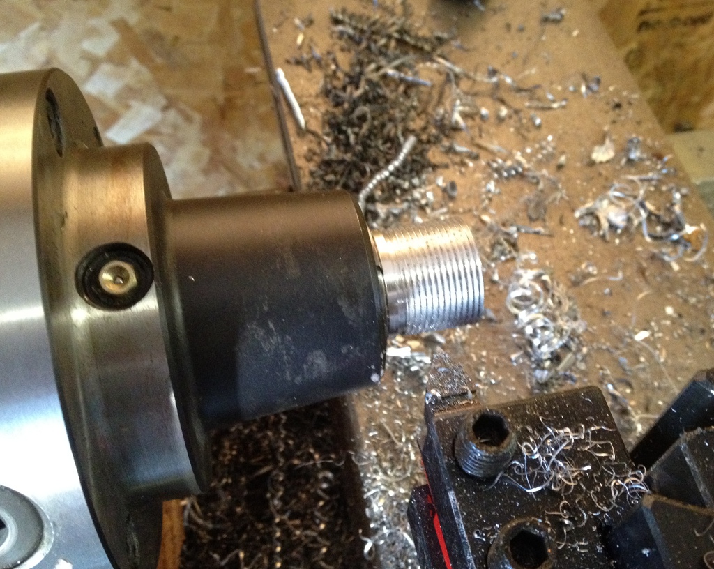
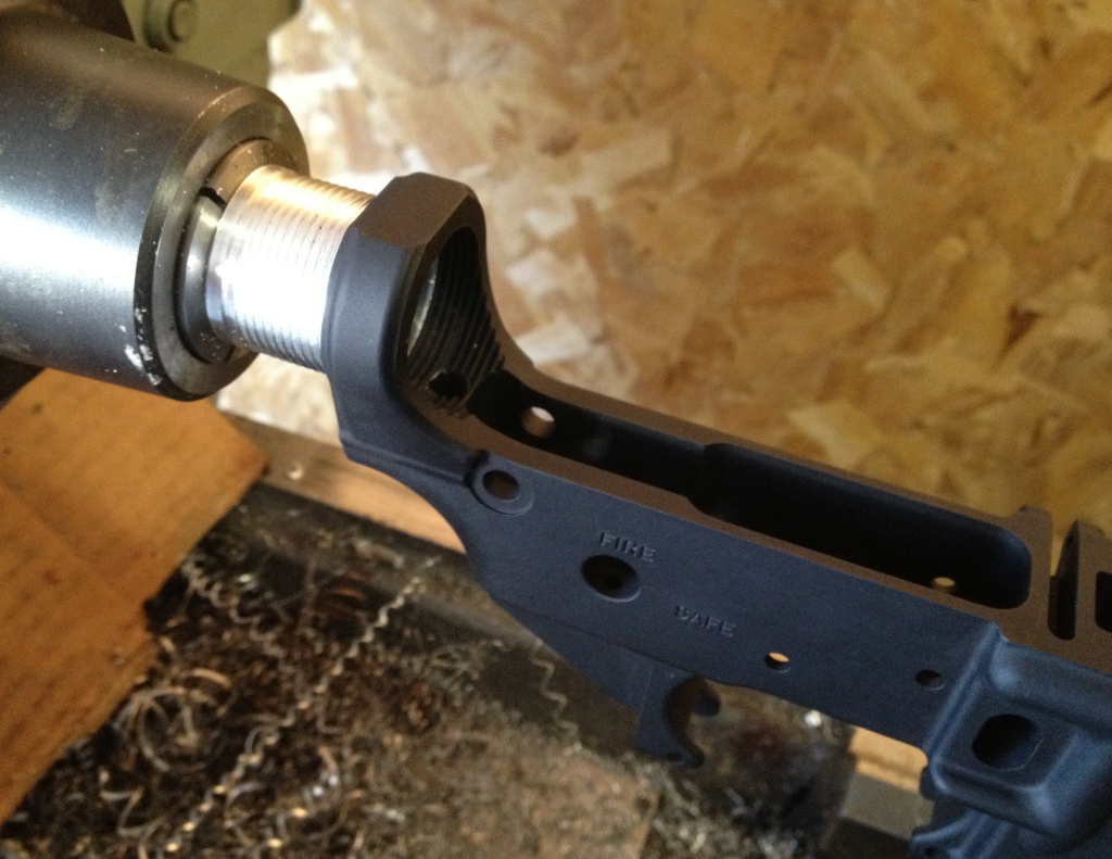
I stuck a piece of 1.25″ scrap aluminum rod in the lathe, and turned some threads onto it.

When the micrometer indicated I was getting close, I threaded on an actual aluminum lower to test for fit.  Afterwards, I opted to fit out the lower with internals as well, as I figured it was prudent to test the untested upper and .22 conversion with a ‘proper’ aluminum lower first.

This morning I hunted around for ammunition, which took me a good 20 minutes (while I am a firearms enthusiast, I don’t think I’ve fired more than a dozen rounds or so in the past 5 years).  After realizing that I had no .22 ammo (yet discovered cartridges for guns that I do not own), I made a stop at the manliest store on the planet to pick some up (if Bruce Campbell were a store, he’d be Fleet Farm).  I then headed to a top secret testing facility (Dad’s farmland) and carefully assembled the upper onto the aluminum lower.  Absolutely nothing had been previously tested, and this was actually the very first AR-15 I’ve assembled (or even owned), so it was with a fair bit of trepidation that I loaded a magazine into the gun (with only a single round – always test unproven systems with a single round to begin with).  After cocking it and carefully letting the bolt forward to chamber the round, everything looked to be in place, so I aimed (as well as one can ‘aim’ with nothing attached to a flattop upper) 20 feet away into the dirt and fired.  Everything worked fine, so I reloaded with 2 rounds and repeated, followed by 3 rounds.  All systems functional!

I switched out the lower for my printed version and double checked the operation.  Would it hold up?  Again, one round in the magazine, cock the gun, squeeze the trigger, and…  Wouldn’t you know it, I shot my eye out.  Just kidding – it functioned perfectly.  Testing again with 2 rounds, then 3 rounds, then a full magazine.  Everything ran just as it should, magazine after magazine.  To be honest, it was acting more reliably than a number of other .22 pistols I’ve shot.  I ran close to 100 rounds through the gun before getting annoyed with not actually being able to aim at anything, and decided to call the experiment an overwhelming success.

To the best of my knowledge, this is the first 3D printed firearm (as per the definition in the GCA) in the world to actually be tested.  However, I have a very hard time believing that it actually is.  My Stratasys is a good 15 years old, and Duke Snider’s original AR-15 CAD files have been floating around on the ‘net since early 2000.  As such, I can’t imagine that I’m the first person stupid adventurous enough to actually pull the trigger on a 3D printed receiver.  If someone has beaten me to it, please leave a comment!

Gunsmithing with a 3D printer – Part 1

I’ve used my Stratasys to prototype out various ideas for paintball gun parts, but the concept of using it for actual firearm parts hadn’t really occurred to me until early last year.  I first thought of making some dummy 12 gauge shells to test out the action on a Remington 870, and then thought of […]

I’ve used my Stratasys to prototype out various ideas for paintball gun parts, but the concept of using it for actual firearm parts hadn’t really occurred to me until early last year.  I first thought of making some dummy 12 gauge shells to test out the action on a Remington 870, and then thought of using it to test out 1911 pistol grip panel ideas.  Gun manufacturers have been using rapid prototyping for years, and the concept is now making its way to the hobbyist gunsmith.  To the best of my knowledge, this has been restricted to mockups (Justin Halford used a stereolithography made frame to test component fit for his fantastic Beretta 92FS project) or less critical parts like furniture (grips, buttstocks and such). It wasn’t until I came across an AR-15 magazine follower on Thingiverse that I began to wonder about the feasibility of making more functional parts with a rapid prototyper.

The use of plastics in firearms is a relatively recent development as far as primary structural components go.  Firearms have certainly used plastics early on (the use of phenolic ‘Bakelite’ was popular for grips and other previously wood furniture in the years leading up to WWII and well afterwards), but use of plastics for a core component took much longer.  Consider a car analogy – we’ve seen plastic dashboards for many decades, but the use of plastic for something as critical as an engine block wasn’t attempted until the early 1980s.  It wasn’t until 1959 that Remington (at the time owned by DuPont, hence having access to cutting edge polymer technology) came out with a .22 rifle that used plastic for the receiver (the core ‘body’ of the gun).  This was the Nylon 66, so-called since the Zytel-101 material used was a type of Nylon 6-6 polymer.  While it was quite a popular rifle (selling over a million units by the time it was discontinued in 1991), and helped further the use of synthetic stocks among shooters, it wasn’t until Glock pistols became popular that polymer firearm frames/receivers gained widespread acceptance.  Today, polymer framed pistols outsell their metallic counterparts, and new rifle designs increasingly use molded synthetic receivers.

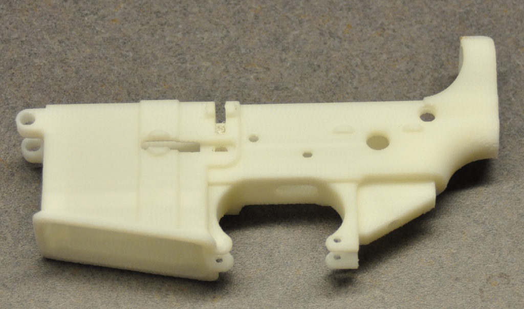
The AR-15 rifle, while designed to use an aluminum lower receiver, has such limited force imparted while firing that I guessed it could probably be made of printed plastic with little worry of breakage.  After all, Orion’s Hammer has successfully made a lower from HDPE (after having limited success making one from a pine board), not to mention the commercially produced polymer receivers such as Bushmaster’s Carbon 15 and Plum Crazy C-15. It would easily fit within the build volume of the Stratasys, but my concern was whether or not it would have enough precision for all features to be usable (Orion’s Hammer didn’t worry about the takedown pin detents or bolt catch, for example).  Rather than waste a lot of material on a failed idea, I took Justin Halford’s IGES file of the lower, scaled it to 75% of full size, and set it running with PP3DP filament.  The resulting print looked fantastic:

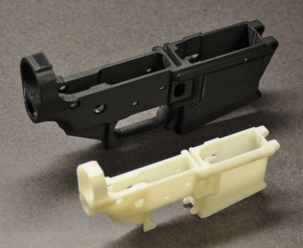
Figuring that my chances with a full scale print were excellent, I decided to modify the model by strengthening two areas that I was slightly concerned about – the front takedown pin lugs and the bolt hold catch lugs.  Adding more material to the model in SolidWorks was pretty straightforward, and I finished it up by adding an integral trigger guard.  I switched out the PP3DP filament for some black Bolson ABS – after all, the ‘black rifle’ would look a bit odd in ivory (more importantly, it’s easier to see/photograph detail on dark material).  After slicing the STL file, I sent it to the Stratasys and waited a few days (no speed demons, these old machines).

After breaking away all of the most easily removed support material, I had a great looking print.  I had generated the STL file at a very high resolution, as I was wondering how well the buffer tube screw threads would actually turn out (having not yet tried printing any threaded objects).  As it happened, perfect!  A buffer tube screwed right into the threads with no cleanup required.  Naturally, I wanted to share my results, but unfortunately firearms are presently a bit of a touchy subject.

The concept of using a 3D printer to manufacture gun parts has not been lost on the RepRap community, and the topic has been debated a number of times on the RepRap forums.  At this point, there is a policy proposal to not allow weapon designs or projects to be uploaded to the RepRap library, and a line on the Health and Safety page for the RepRap project states “the RepRap researchers will work actively to inhibit and to subvert the use of RepRap for weapons production” (emphasis mine).  On the other hand, Thingiverse once had a rule against weapons in their terms of service, but later removed that restriction.  Afterwards, the Thingiverse upload page still said “Please don’t upload weapons. The world has plenty of weapons already,” but I assumed that this text was not updated after the TOS was revised.

I decided to ask for clarification on the Thingiverse mailing list.  The phrase “kicking the hornets’ nest” aptly describes the resulting discussion, I think.  In the end, Zach ‘Hoeken’ Smith (one of the Thingiverse founders) weighed in and clarified that such content is allowed, though discouraged. Fair enough. Apparently someone had taken notice of the commotion, and three weeks later, there was an STL file of a lower receiver posted to Thingiverse in what could be described as a confrontational manner.  Since the cat was out of the bag, I decided to upload my own STL model, as I wanted to hear constructive feedback on how the version might be improved to better suit the current limitations of 3D printing.  Well, apparently the resulting ‘weapons on Thingiverse’ debate raged hard enough that in February the lawyers were unleashed upon the site’s Terms of Use, and now uploading any content that “…contributes to the creation of weapons…” is verboten. Although that policy doesn’t appear to be enforced, I suppose they could yank my uploads and kill my account at any time, hence I’m re-documenting my work here.  Enough rabble-rousing – back to the fun stuff.

I’m rather jealous of people who can print the lower receiver with soluble support, as clearing support material from small diameter holes is a bit of a pain.  I used a pin vise and an assortment of small diameter drill bits to clear out all the long cross drilled holes in the part, using Duke Snider’s receiver blueprint for dimension references.  With all traces of gray polystyrene eradicated, I set about cleaning up the larger holes, as they were ever so slightly undersized (better than being oversized).  I ran a 5/32″ drill bit through the holes for the trigger and hammer pins, and eagerly installed the fire control group.  The trigger and hammer  functioned flawlessly, with no slop apparent in the pins.  The selector lever was a bit of a tight fit, so I worked it back and forth perhaps a hundred times to break it in.  After tapping the 1/4-28 thread for the grip screw, I attached the grip, keeping the selector in place by virtue of its detent.  Similarly, the magazine catch was a bit of a tight fit, and I had to carefully work the part back and forth in the receiver to make sure that it would reliably retract under force from the magazine release spring.  I then ran a 1/4″ drill bit through the holes for the front and rear takedown pins.  Unfortunately, I heard a quiet snap when drilling out the front hole, and sure enough, there was a break between layers.

On the plus side, this confirmed my suspicion that the takedown lugs needed reinforcement in the first place.  I brushed on a bit of Weld-On 3 to fuse the layers together (delicately, recalling what happened when I dunked printed parts in MEK).  After running a drill bit through once more, the cleanup was complete, and I installed the takedown pin with its spring and detent.

Nice!  Now, for the other area that had given me concern – the bolt hold lugs.  Sure enough, when I pressed in the roll pin, I had layer separation.

Well, I never cared much for roll pins anyhow – they always seemed rather brutal (especially when driven into a blind hole – yikes).  After touching up the damage with a few more dabs of Weld-On 3, I ran a 3/32″ drill bit through the hole.  I then threw away the roll pin and instead used a dowel pin of the same size.

A little bit of superglue on either end of the pin should suffice to keep it in place.  Finally, there was the rear takedown pin to contend with.  Justin’s model appears to have the recess for the pin head as around 5/16″ or so, while the head on the pin from my DPMS parts kit measures 3/8″.  No worries – I lightly clamped the receiver in the mill vise, centered the spindle over the hole, and carefully widened the counterbore out with a 3/8″ endmill.

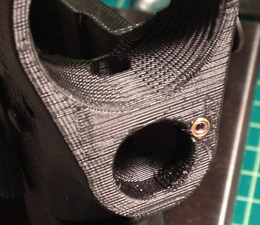
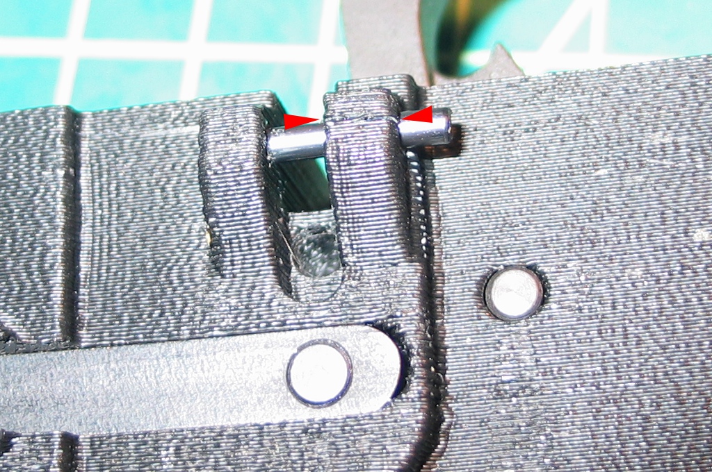
After this, the takedown pin fit perfectly.  Since I don’t actually have a full AR-15 stock (and will be attempting to run this receiver as a pistol first), I needed a way to capture the detent spring for the rear takedown pin.  I opted to tap 4-40 threads in the rear of the spring hole and kept the detent and spring in place with a 1/8″ long 4-40 set screw.  Unfortunately, the force on the detent was heavy enough that when I tried to slide the takedown pin into the receiver, the detent broke through the thin wall into the rear of the FCG area.  It appears that extra 1/8″ of spring compression due to the set screw may be too much.

I dabbed on a bit of ye olde Weld-On 3 and clipped 1/8″ off of the spring to compensate before attempting to secure the pin again, but the detent still wanted to break through the wall.  I’ll leave it out for the time being, but I’m considering drilling the hole out larger and sleeving it with brass tubing.

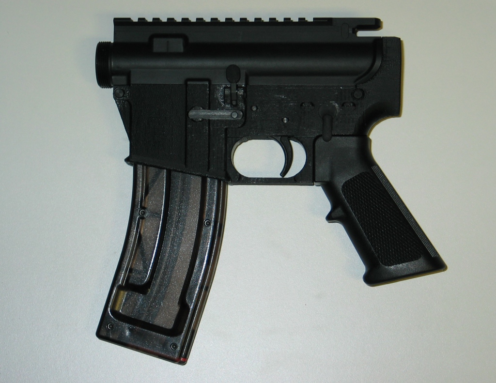
Overall, it’s looking quite promising.  The upper receiver fits snugly, and magazines can be inserted and removed with ease – shown is the lower with an upper attached along with a .22 magazine that I intend to use with the CMMG .22 conversion kit.

Successful pod covers

The other day I finally cracked open the molds to see how things had turned out with my wing pod and tail skid. A few air bubbles here, and a lot of weave texture showing through – this is no substitute for vacuum bagging, but will it at least be sufficient? Oh noes!  Only two […]

The other day I finally cracked open the molds to see how things had turned out with my wing pod and tail skid.

A few air bubbles here, and a lot of weave texture showing through – this is no substitute for vacuum bagging, but will it at least be sufficient?

Oh noes!  Only two lightweight fiberglass layers were apparently not enough – while flexible enough to be removed from the core, the molded part just wasn’t strong enough to hold up to the tugging and pulling needed to free it.  On the plus side, the fact that it was able to be fully removed means that the waxing and PVA application was sufficient to keep from ruining the plug, so this was promising for the wing pod.

My ‘kinetic separation method’ for breaking the mold halves apart (whack it on the floor a few times) is still far from ideal, as another corner broke off of the mold.  I now see why people who know what they’re doing build in screwdriver slots so that the halves can be separated in a less destructive manner.  With the satisfying sound of PVA breaking away from a surface, the halves popped free.  The part was still adhered to the female mold half (as evidenced by the black center), but a little careful pulling finally extracted it.

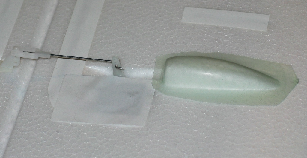
Finally, a completed, intact part!  Now, would it fit…

Almost perfect!  There’s a tiny bit of side-to-side slop, but I’d say this is well more than “good enough”.  Now, to make 3 more!

Shaving weight on the Diamond 2500

One thing I’ve noticed about EZ-LAM 60 epoxy is that the maker wasn’t lying about not using it when the ambient temperature is under 65 °F.  It’s now been over 48 hours since I laid up the two pod molds, and the fiberglass/epoxy is still slightly pliable.  I’m sure in another week or so when […]

One thing I’ve noticed about EZ-LAM 60 epoxy is that the maker wasn’t lying about not using it when the ambient temperature is under 65 °F.  It’s now been over 48 hours since I laid up the two pod molds, and the fiberglass/epoxy is still slightly pliable.  I’m sure in another week or so when standard late spring temperatures finally arrive the epoxy will fully cure in 24 hours when in my basement, but for the colder parts of the year I’ll need to use EZ-LAM 30 or just start experimenting with the West System hardeners.  As such, this is a quickie post on removing the weights from the Diamond 2500 powered sailplane.

I hate seeing RC planes come from the factory with a bunch of steel washers glued into the nose – if the plane has the center of gravity too far back, I’d rather add more fuel to the front (in the form of a bigger battery) than dead weight.  I think I know why manufacturers do this, however – they want to be absolutely certain that the plane is stable, even if it means reduced performance.  “A nose heavy plane flies poorly; A tail heavy plane flies once” is the adage I’ve heard a number of times.  As such, I used to fret about having too little weight in the nose, while now I find myself pushing the CG on my planes further and further back to improve the glide slope.

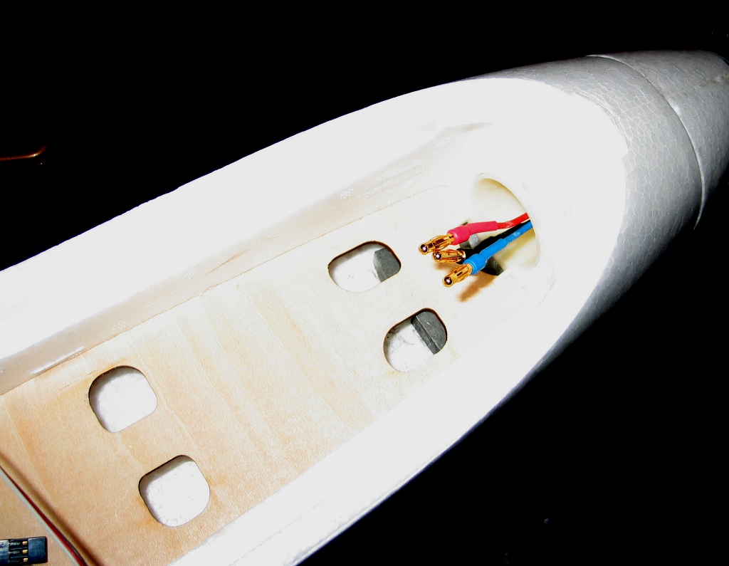
The Diamond 2500 has a pair of steel blocks glued into the nose under the plywood battery tray at the very front (visible just under the motor wires):

Unfortunately, the plywood tray can’t be removed to get at the weights, but with a flat bladed screwdriver and an assortment of picks, I was able to extract them from the rear of the cockpit area (fortunately they weren’t glued in very securely).

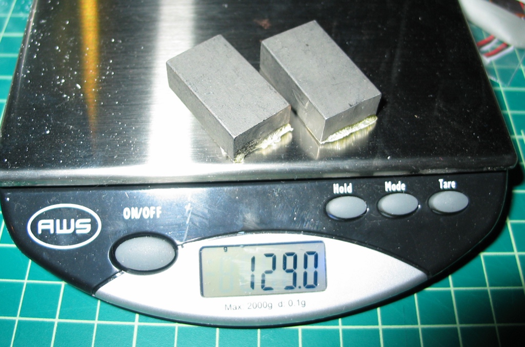
129 grams of dead weight!  Not only is there nose weight in the Diamond 2500, but there are wingtip weights as well!  Supposedly this is to reduce the roll rate, but with a big 2.5m wingspan, I can’t imagine that the roll rate is all that blazing in the first place.

The wingtip weights are glued in a little more securely than the nose weights, so I epoxied a steel rod to the weight to pull it out.  After removing the weights, I glued a small block of white foam in the cavities.

Every little bit helps, as I intend to put plenty of FPV gear on this airframe.  One final bit of weight reduction is the wing spar, which is a length of thick wall aluminum tubing (which slides into square steel tubes inside the wings – I’d love to remove them, but both are glued in quite securely).  The aluminum spar weighs in at 133.8g, but the Goodwinds 020979 carbon fiber tube (which is a perfect fit in both length and diameter) is a mere 58.9g.  All told, these weight reductions add up to nearly 9 ounces – that’s the weight of a 2500mAh 4S LiPo battery pack!


Addendum – 9OCT2015

I’m rather embarrassed to say that even though I posted this several years ago, I still have yet to actually fly the plane.  However, I did just get a very helpful message from Marc Merlin, who offers some great information regarding a newer offering of the plane, a better source of the carbon fiber spar, and a full-scale pilot’s take on doing FPV flights over Burning Man!  Thanks, Marc!

Howdy,

First thanks for your page.

I bought a BFG2600 since the diamond 2500 isn't for sale anymore, and that
one comes with small steel balls in the wings, and nothing in the front,
likely because the motor is a bit bigger.

It does however come with a horrible heavy steel rod, but when I tried to
replace it, Goodwinds 020979 doesn't work anymore as they have discontinued
metric sizes.

After much searching (really, this took a while), I finally found this:
http://www.rockwestcomposites.com/products/t-rnd-472
and they're a perfect fit.

They sell them in 2m length, but I ordered them pre-cut at 83cm, giving me 2
tubes plus a leftover for some other project.

Would you mind updating your blog post to point people to that tube instead
and save them the time I spent?

This is my BFG2600 BTW
http://marc.merlins.org/perso/rc/post_2015-08-15_BFG2600-FPV-build-with-Pixhawk-Ardupilot-3_3-_Diamond-2500-remake-from-Hobbyking_.html

and this is the trouble I got into with it
http://marc.merlins.org/perso/rc/post_2015-09-01_Flights-over-Burning-Man_-and-the-current-unfortunate-BMorg-and-FAA-policies.html

Cheers,
Marc

Fixing a major mistake

After sawing the halves of my pod mold apart, the first thing I did was to fit the two halves together to see just how much clearance there was (should be right about 0.010″).  Unfortunately, this is what I got: The two halves should fit fully together with no gap, so I started trying to […]

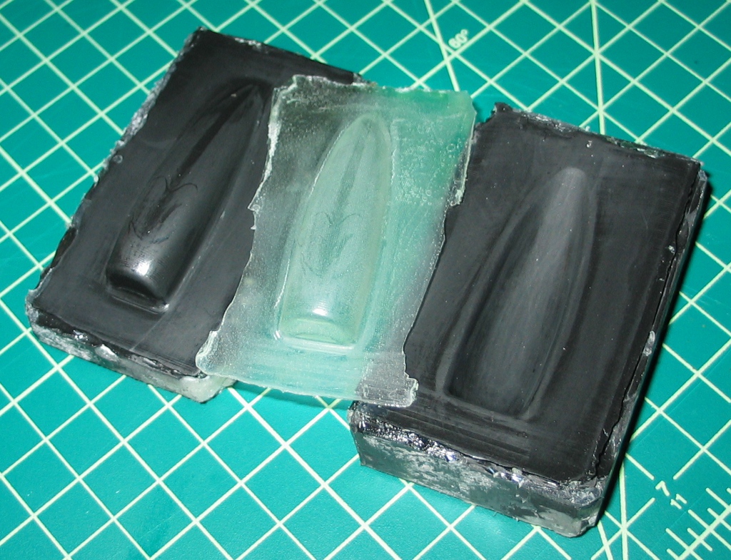
After sawing the halves of my pod mold apart, the first thing I did was to fit the two halves together to see just how much clearance there was (should be right about 0.010″).  Unfortunately, this is what I got:

The two halves should fit fully together with no gap, so I started trying to figure out what went wrong.  As it turned out, this was simply a result of picking precisely the wrong surfaces to be machined, and I wound up with the exact inverse of what I wanted.  I was guessing that I’d have to simply recut the molds (I say ‘simply’, but it would be kind of a pain), until I realized that I should be able to simply make molds from the molds, thus flipping the surfaces back to how they’re supposed to be by turning the male half into a female half and vise versa.  Copying molds in this way is not uncommon for composite work – a male master or ‘plug’ might have a number of molds pulled from it, with each mold being used to create dozens or perhaps hundreds of parts before it starts getting warped or damaged.  If another mold is needed, you simply cast a new one from the master.

The first step was to polish the surfaces (which I would have had to do without a screw-up anyhow), for which I wet sanded each half with 400 grit sandpaper to eliminate the ridges left from machining (I could have done a little better, as there are some ridges left, but I think it will certainly be good enough).  After that, I applied a coat of Partall #2 and buffed it off. After applying and buffing 4 more coats (to ensure that there are no missed spots – if the epoxy adheres to the mold surface itself, you have a ruined mold), I was ready to apply a coat of PVA. I diluted the PVA about halfway with distilled water and then brushed it on the surfaces with an acid brush, then set the parts aside to dry (you can see the green tint of the PVA pooling in low spots on the Corian mold halves).

Next I needed to dam up the sides of each half, so I used some sheet foam and hot glue, taking care to leave no gaps between the Corian and foam (lest epoxy leak out the side).

Then it was time to mix up some tooling resin, which is basically just epoxy mixed with graphite powder to provide a nice dark surface (which makes it easier to see when you have fiberglass properly wet out against the mold surface).  I used a little bit of West 404 filler as well to thicken the mix a little.

I carefully brushed the tooling coat over the entire mold surface and up the sides of the walls.  I then poured the remaining resin into each half, and took a blurry photo.

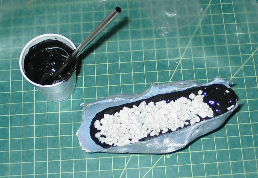
I tossed the halves into the oven for an hour on a very low temperature to help the epoxy ‘kick’ and start polymerizing (which is what actually causes it to harden).  With the tooling coat thickened, I was ready to fill in the remainder.  Since epoxy is expensive (and epoxy fillers aren’t cheap, though certainly less costly than the epoxy itself), I figured I’d try using aquarium gravel as an aggregate filler since it comes in relatively small bags for just a few bucks.  I mixed in a bit of 404 filler as well, though my mixes were a bit unbalanced – one half was gravel poor, while the other had an abundance.

The aquarium gravel turned out to be not as strong as I’d like (it chips and breaks easily), so perhaps I’ll just use sand as a filler in the future.  After letting the halves cure for a day, I used a utility knife to slice away the foam dams and a pick to dig out the hot glue.  In retrospect, I should have really used plasticine clay, as the hot glue was difficult to remove.  Separating the Corian master from the epoxy mold was simple, if brutal – just whack the block on a hard surface a few times until the epoxy half pops away (this was how I discovered that the aquarium gravel isn’t the greatest in a structural sense).

When I had a look at the molded halves, I was amazed at the level of detail captured by the resin – not only the minute milling ridges in the Corian and smoother areas where I had wet-sanded were visible, but even the edge of the puddle of dried PVA could be clearly seen.  I did a little more wet sanding on these halves, then applied 5 coats of wax, and then a coat of PVA (this time standing the mold halves up on end to keep the PVA from puddling).

Meanwhile, I realized I had neglected another part of the sailplane that will probably take a bit of wear from landings – the tail skid.  While there is a strip of plywood embedded, I’m sure large gouges in the foam will result the first time I miss a grassy landing strip and plow through a gravel driveway.  Rather than haul the fuse back over to Frankie’s studio to digitize the tail, I thought I’d try making a flexible mold with some OOMOO 25 silicone rubber that was past its shelf life – best to put it to use than throw it out.

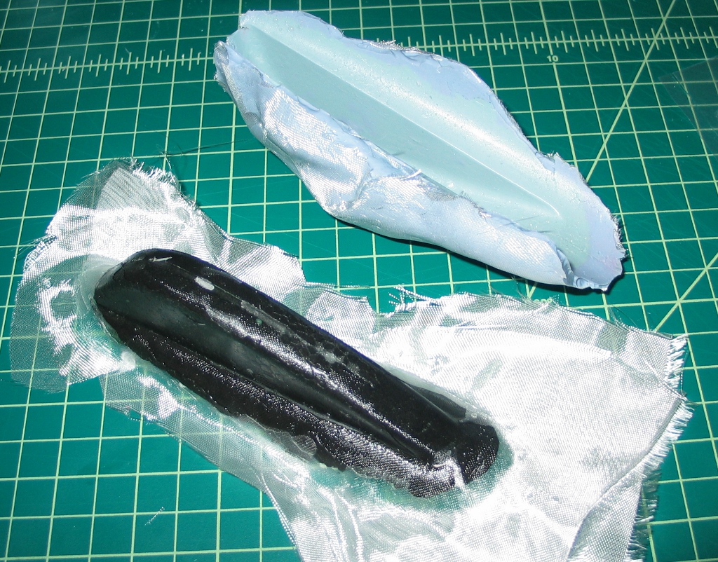
I brushed it on the tail skid and threw in a few strips of fiberglass to give it a little more strength (a technique I recall seeing in a book long ago where strips of burlap were used to strengthen and stiffen a latex mold).  The silicone started setting up quickly, so I blobbed the remainder on and covered it with another piece of fiberglass.

Once cured, the silicone popped right off the tail skid.

I then made a plug in the silicone mold, using more aquarium gravel for bulk.

Just as with the foam, the silicone separated very easily from the cured epoxy.  Note that the texture of the original foam is perfectly captured.  The plug was thoroughly waxed, brushed with PVA, and set aside to dry.

Tonight I finally attempted using both the wing pod and tail skid molds to make actual parts.  I used a layer of 3oz and a layer of 1.4oz glass for the wing pod and mashed the mold halves together (I should clamp them together, but they seemed to be sticking together quite well on their own).  The 3oz glass wasn’t draping well over the tail skid plug, so I abandoned that weight and went with a layer of 1.4oz. and a layer of 0.75oz.  Trying to fit the silicone mold over the fiberglass covered plug was a bit tricky, as the shape doesn’t ‘key’ together as well as it could, but I finally called it good enough and set it aside to cure.  In 2 or 3 days I’ll see if all this work has actually yielded anything useful when I crack open the molds.

Reverse engineering for molds

On the Diamond 2500 powered sailplane, there are small ‘pods’ on the underside of the wings in front of the servos for the flaps and ailerons.  I’m guessing that these pods are intended to serve as some form of protection for the servo arm and linkage on landing, but the problem is that the pods […]

On the Diamond 2500 powered sailplane, there are small ‘pods’ on the underside of the wings in front of the servos for the flaps and ailerons.  I’m guessing that these pods are intended to serve as some form of protection for the servo arm and linkage on landing, but the problem is that the pods will then be torn to smithereens (being foam, just like the rest of the wing).  While my quest to protect these 4 measly foam bumps seems to be ever-increasing overkill, it’s turning out to be a fun project and I’m learning a number of new skills from it.

While there were several ways to approach this, I decided to try making conformal covers for these pods out of fiberglass.  I could have just applied fiberglass directly over the pods, but I wanted to try something a little more precise (and replaceable, though I don’t know why I’m clinging to that notion when the plane is likely to be damaged in far more horrific ways).  I’ve been watching Tom Siler’s work on building his own fully molded F3K competition planes, and his videos are fascinating. He uses Corian for his molds, as it machines really nicely and is easily sanded and polished to provide an excellent finish on the composite parts pulled from the molds. I don’t yet have a vacuum system to bag parts, but I figured if I made a 2-piece mold, I could perfectly form pod covers without needing any sort of vacuum.

First things first – I needed to model the pod in SolidWorks.  Normally I just grab my calipers, radius gauges and other measuring tools, but the pod had me stymied – it’s a more complex feature than I initially thought and isn’t as simple as a truncated swept profile.  What’s worse is that it’s located on an airfoil, so I don’t even have a flat plane to reference.  I started to consider making a rubber mold of the pod, then casting an epoxy plug from the mold, then digitizing the plug with the touchprobe I have for the Taig (but have yet to finish wiring up), but that was turning into quite a production.  I remembered that one of Frankie’s toys is a NextEngine scanner, which would be perfect for this application, so I took the wing along during one of our Zcorp hacking sessions.

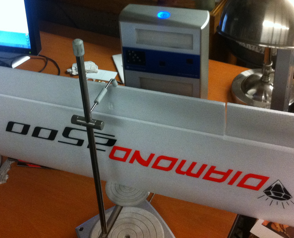
First step was to position the wing in front of the scanner itself.  The base will automatically rotate in increments if needed, but I just needed a 1-pass scan.

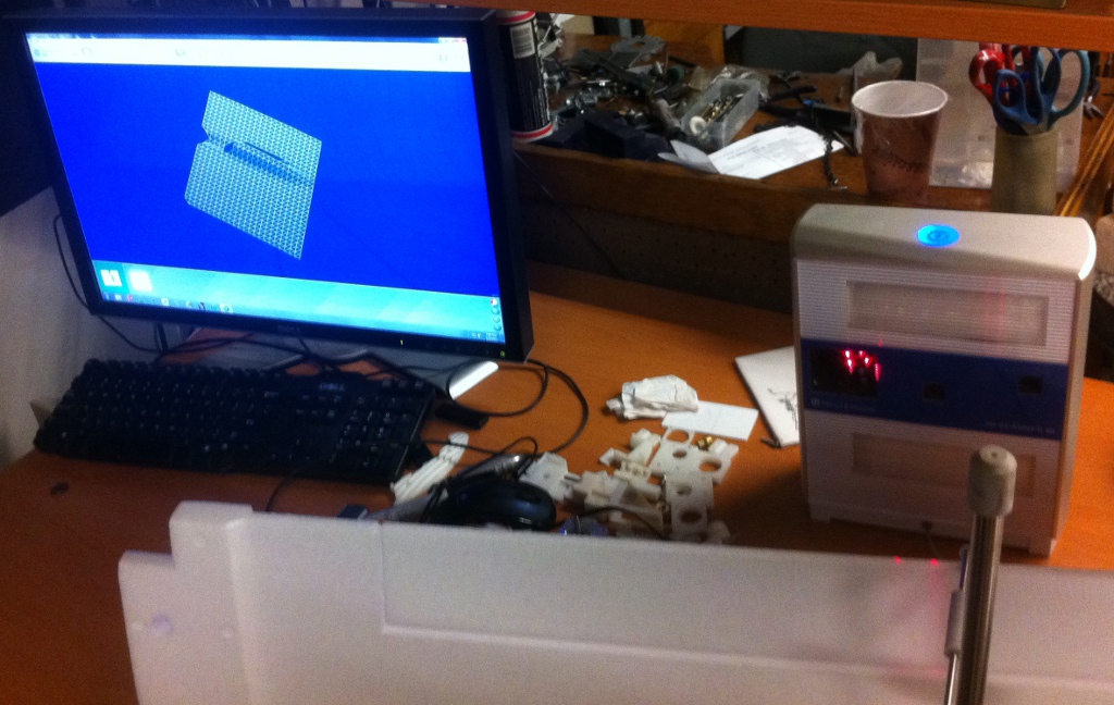
Once in place, let the scanner rip – a few of the laser beams are visible sweeping over the scan area, and the monitor screen shows a rough pass of the scanned pod.

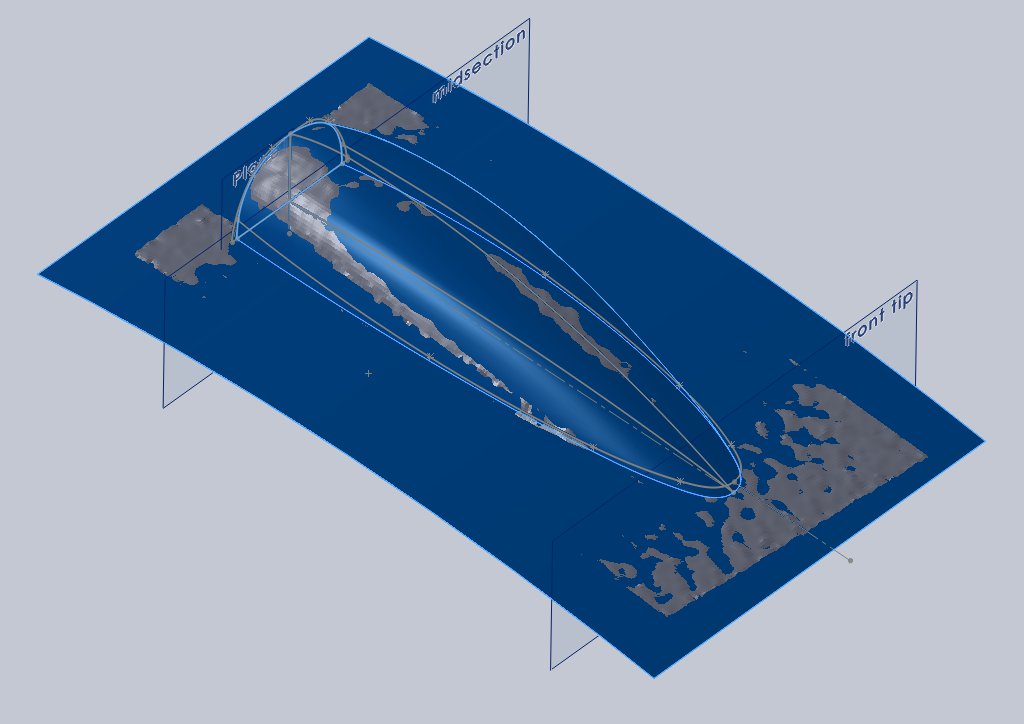
I brought the generated STL into MeshLab and did some minor cleanup before bringing it into SolidWorks.  SolidWorks actually has some impressive mesh-to-surface capabilities, but since I was working with a mesh with a few holes in it, it would have taken a bit of work to get usable output (and I didn’t see a way to define a symmetry plane, but maybe I didn’t look hard enough).

Instead, I did my own surfacing, which took me quite a while.  I’m not good at it, and I know some of my techniques are wrong, but the final output should serve its intended function.

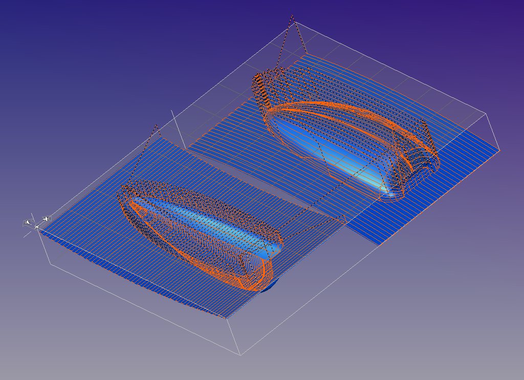
After finishing the male side of the mold, I thickened the surface by 0.010″  (I figure that should be plenty of fiberglass) to create a solid and extracted the far surface as the female side of the mold.  I set the two halves side-by-side in an assembly and exported it to GibbsCAM.

Once in Gibbs, I created my toolpaths (this shows the paths for the second operation, which uses a 0.250″ ball end mill).  After posting the file, I was finally ready to start cutting material.

Not having yet found any 1″ thick scrap Corian (everything I’ve gotten is 1/2″), I glued two pieces together.  The cold temperatures meant that the epoxy hadn’t fully cured after 24 hours, so I stuck it in front of a space heater for a day, and that firmed everything right up.

I drilled and counterbored mounting holes and then bolted the block to the tooling plate on the Taig.  This shows the results of the first pass, which was roughed with a 0.250″ flat end mill.  Note the curvature in the parting plane to match the airfoil surface.

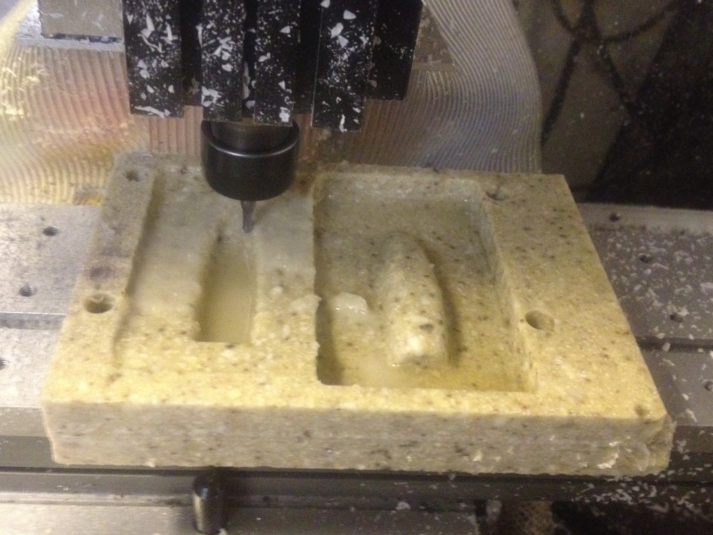
This is the third and final pass, which used a 0.125″ ball end mill (and a generous amount of WD-40 as cutting fluid).

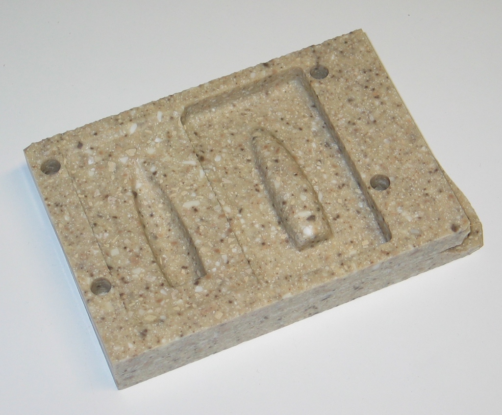
Once washed off, this is the result.  The pattern of the Corian makes it impossible to see any fine detail in the photo, but the surface finish is phenomenal – I used a 0.010″ stepover for the final pass (overkill, but it’s my CNC, so I’m not paying any extra for machine time) and it looks superb when you hold the machined surfaces up to the light.  All that remains now is to chop the two halves apart, then sand and polish the mold surfaces.

Just one word… Are you listening?… Composites.

‘Composites’ (which for a very long time I mistakenly equated with ‘carbon fiber’) were always one of those mysterious materials to me – rare, expensive, difficult to work with, but with incredible strength. Something of a real-world parallel to Mithril or Adamantium, if you will. It turns out that there’s nothing really magic about it […]

‘Composites’ (which for a very long time I mistakenly equated with ‘carbon fiber’) were always one of those mysterious materials to me – rare, expensive, difficult to work with, but with incredible strength. Something of a real-world parallel to Mithril or Adamantium, if you will. It turns out that there’s nothing really magic about it (though production of carbon fibers is still difficult and expensive) when you consider that the hard fiberglass chairs in a school cafeteria are composite (the fiberglass being the base reinforcing material and the epoxy being the binding matrix).  I always wanted to learn more about composite fabrication methods, and lately I’ve been learning more than I perhaps wanted to.

It started with stumbling across a video of some East European F3K competitors having a bit of fun with their DLGs (F3K is a class of aeromodeling competition with hand launched RC gliders). I never had any sort of interest in gliders whatsoever – if it didn’t have a motor, what fun could it be? But after watching the video and seeing the incredible capabilities of a 1.5m airframe that you hurl into the air yourself, I was intrigued. I attended a DLG contest in September to learn more about this particular segment of RC flying, and was smitten with the graceful purity of unpowered flight.  I now understand what some people see in ballet – I simply had to experience it in a form I could comprehend.  After the contest, I decided that I’d like to give it a try myself. Fortunately, Steve Meyer, one of the fellows at the contest (a seasoned competitor who actually qualified for the USA 2011 team) had an old plane that he was willing to sell for a good price and a few weeks later I had my own DLG to try out. Launching it the first few times was equal parts terror and exhilaration, but I started to get the hang of things quickly enough and even managed to catch it a few times (outside square loops on the other hand, well, I’ll give that one a few years). I gained more valuable experience in RC flight during the first half hour with the DLG than I had all summer. I then began to fly it every chance I could get, though the creeping wind and colder weather kept thermals to a minimum. On the last reasonably warm weekend of November, I was flying at the local park, trying to put more power into my launches. When spinning around, my fingers slipped off the launch peg, and I felt more than heard a sickening crack as the plane made a beeline right for the nearest swingset. In retrospect, I had enough time to get my fingers on the sticks and pull up, but was shocked enough that all I could do was watch the impact.

Would you believe that this is what it looked like post-impact?  Incredibly, airframe damage was pretty minor – a few small creases on the wings, ailerons and horizontal stabilizer.  Really a tribute to the sturdy design of Dr. Mark Drela and Aradhana Singh Khalsa’s beautiful execution of it in kit form (and certainly Steve’s expert assembly of the Light Hawk II).  The right aileron servo was completely stripped, but I hoped that it wouldn’t be too horrific to replace and ordered a new Dymond D47 while I surveyed the rest of the damage.

This is the worst of it – a crease on the underside of the right wing (with a slightly smaller matching crease on the top surface), and the reflective tape removed to reveal the stripped servo.  The servo has been glued in place, so I’ll need to Drem-mill (Drem-mill?  Dremel? Get it? Eh?  Er, never mind…) it out of the pocket.  Fixing the crease itself would probably be easy, but fixing it well seems a more daunting task.  Steaming small dents out of the wing (which is a high strength blue foam covered in Kevlar) works quite well, I found – just pour boiling water over the dent, and the foam magically reverts to an undamaged state (or use an iron pressed against a wet paper towel on the wing).  These creases however, don’t steam out – trust me, I tried.  So I’m saving them for later while I get up to speed with the basics of composites.

This is the left wingtip, where the launch peg is located.  You grasp the peg with your index and middle fingers, whirl around, and release the plane (a left handed pilot would have the launch peg on the right wing).  I think the crease in the Kevlar skin just above the peg may be the result of the sickening crack I felt/heard (honestly, I though the peg itself had snapped off).  From what I’ve read, this is caused by swinging your arm downward on release (a natural movement, as it’s how you would throw a baseball).  This makes sense, as the buckling happened only on the underside of the wing.  My plan is to poke a few small holes into the crease, use a syringe to inject epoxy into the damaged area and clamp it to a flat surface while it cures.

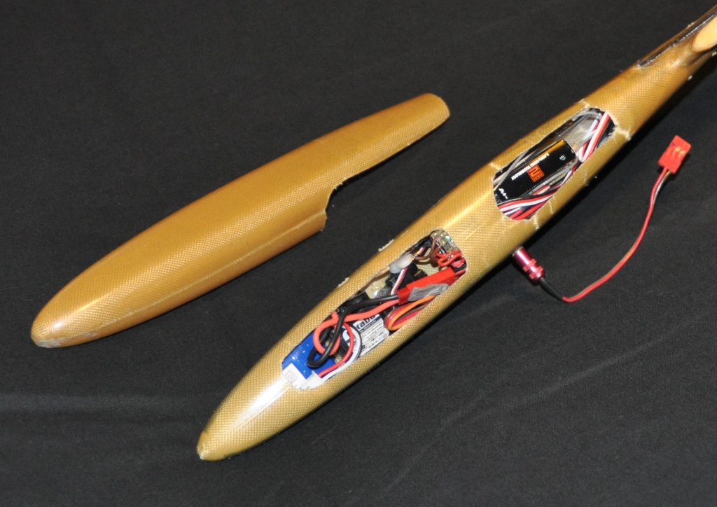
For anyone wondering “why is it made out of Kevlar – you expecting to be shot at?  Har har!” – this is the reason.   The nose took the brunt of the impact from what I can tell, and you can see the cracks at the 4 corners of the rear cutout of the pod where the epoxy matrix entirely failed.  If this was just carbon fiber or fiberglass, I’d have a lot of pieces and fragments in the photo and would be looking for a whole new plane.  Carbon and glass are strong but brittle, while Kevlar is extremely tough and the fibers will remain intact to hold the airframe together even with such damage.  The nose is one of the most interesting parts of a DLG, if for nothing else than the sheer density of components.  The battery is crammed all the way forward with two small servos behind it (I don’t even want to think of the difficulty in getting the control rods connected), followed by a voltage regulator and low voltage beeper, with the radio receiver bringing up the rear.  There’s even a ballast tube further back sized for tungsten weights, but I haven’t even gotten to that point yet.  The red cord coming off the side of the nose is the charging plug, which you remove to turn on the electronics (this eliminates a standard power switch, saving precious grams).  Custom wing airfoils, specific weave patterns of fabrics, CNC made molds for airframe components – these are standard fare for top competitors, making DLGs truly the F1 cars of the air.

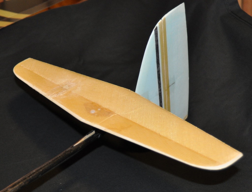
So as a new driver with a broken F1 car, it seemed prudent to start small on the repairs.  The vertical stabilizer and rudder (light blue) were unscathed, but the tailplane (in yellow-brown Kevlar) sustained a very slight crease just to its left of the centerline.  It was in good company – Steve had pointed out the damage on the right side and had explained to me how he fixed it with a little scrap of lightweight fiberglass cloth and CA (CA is short for short for cyanoacrylate, better known as ‘superglue’ for those who don’t frequent hobby shops or RCG).  I steamed out the crease as much as I could, and then applied a small rectangular patch of fiberglass cloth wetted with foam safe CA (regular CA will partially dissolve polystyrene foam, so you have to be a bit careful with adhesive choices).

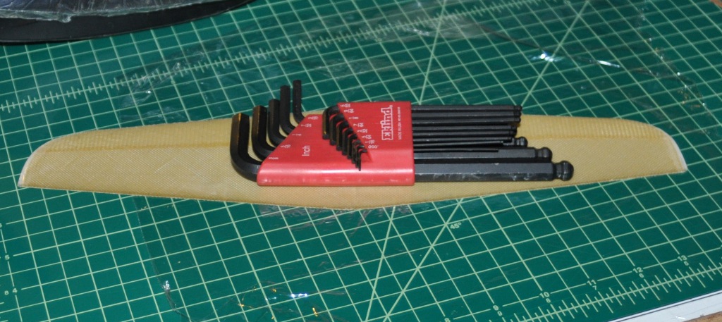
I used a hex wrench set as a weight to keep the stabilizer flat as the CA cured (a piece of kitchen plastic wrap keeps it from bonding to the cutting mat).

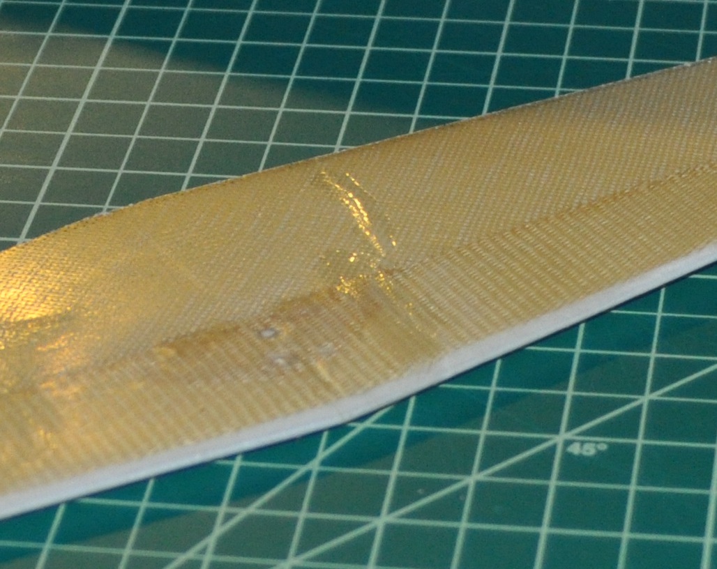
The fix turned out quite well, and I had to position this shot just so in order to glint the light off of the repaired area.  The ever-so-slight delamination of the Kevlar from the foam core is no more, and the tailplane is ready for action.  Still, the rest of the airframe remains.  I decided that getting up to speed with epoxy and fiberglass would be worthwhile before diving into more involved repairs.

One aircraft I’m preparing for the upcoming flying season is a Diamond 2500, which is a giant (at least as far as I’m used to) 2.5m powered sailplane. I chose it because my 2m Radian has gotten a bit boring, and because I wanted a good platform for FPV flying. The Diamond 2500 has a generous amount of room in the fuselage for extra gear, and I’m thinking of making a replacement canopy/cover that has the camera and associated equipment attached (so I can easily swap back and forth between camera ship and sport flyer). So the first thing I tried was to just make a rough copy of the existing canopy.

I started with a piece of plastic wrap taped over the canopy (it easily peels away from cured epoxy) and then draped a piece of 1.4oz (the weight for a square yard of material) fiberglass cloth over the canopy and carefully wetted it out with laminating epoxy by using an acid brush.  Once that layer was done, I thought I’d be adventurous and put down a strip of Kevlar tape (which is just the name for a ribbon of woven material – there’s no adhesive involved), which I also wetted out.  Finally, I added one more piece of 1.4oz fiberglass and wetted that out, then covered the whole thing with another piece of plastic wrap (hoping that it would help squish down the layers).  Well, I now see the value in vacuum bagging, as the Kevlar strip has air inclusions all along it (you can see that it’s only partially wetted out in the center).  I was trying not to overdo the resin (very dry layups are the norm when building DLG gliders – every gram counts), but without bagging, there’s no good way to eliminate the trapped air without simply adding more epoxy.

Once I peeled off all the plastic wrap and trimmed the edges, it didn’t look that awful for a first attempt.  Rather floppy, though – a little less rigid than if it were made from blister pack plastic.  Still, I had absolutely zero concept previously of how a completed part would feel, so now I know that more layers are needed to get the rigidity I need for the part (and that skipping the Kevlar tape is a good idea).

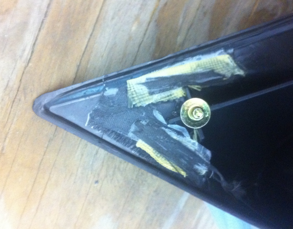
Now that I have some bits of fiberglass, carbon fiber and Kevlar, I realize how useful these can be in simple household repairs.  Superglue and epoxy by themselves rarely hold up as well as hoped, but adding a bit of reinforcement can do wonders.  On a replacement rearview mirror I purchased for my truck, the plastic tip was broken off in the package.  I figured a superglue-only repair would likely fail in short order, so I used a few small pieces of Kevlar and carbon fiber tow sandwiched between patches of fiberglass to act as reinforcement.  Dousing them all with CA and letting it cure provided a reasonably stout repair that has held up just fine for several months (and will probably outlast the truck itself).

Ugly, but far more expedient than getting a replacement (and being on the backside of the part, nobody will see it anyhow).