I’ve been rather fascinated lately with the RepRap project. In a nutshell, this is a project to build a low-cost rapid prototyping machine. Specifically, RepRap aims to design and build rapid prototypers that can make as many of their own parts as possible, which is a noble goal, but not a design facet that particularly interests me right now. There are other rapid prototyping projects such as Fab@Home and Makerbot’sCupCake CNC (which is based on the earlier RepRap design known as ‘Darwin’), but the latest RepRap design known as ‘Mendel’ is really elegant. Mendel is a far simpler design than its predecessor, has a larger working envelope, and should prove far more scalable – stretching any of the axes for more travel should be pretty trivial if the design ever needs expansion for making larger parts.
Ideally, building a Mendel for myself would start with getting a set of rapid prototyped Mendel parts from someone else, but there seems to be hardly anyone making Mendel parts yet. Besides, I really have no interest in having a ‘pure’ machine that was replicated as much as possible – in fact, I’d prefer to actually machine my own parts for it. I’ve been eagerly following Shane Wighton’s blog, as he also wanted to build a Mendel and has access to a machine shop. We both came across the same issue of trying to view the 3D assembly of Mendel in the downloadable solid model files – the files were created in an academic licensed version of Solid Edge, which the freely downloadable Solid Edge Viewer refuses to display. I thought perhaps it was a video driver issue until I tried running the program on another machine. A student friend who has access to an academic version at school was kind enough to create an eDrawings version of the assembly for me. I’ve used eDrawings created from SolidWorks many times, and they work beautifully. However, the .easm created from a trial copy of eDrawings for Solid Edge was abyssmal. Missing parts galore, including one of the steppers (why it singled out a single stepper is beyond me – they’re all from the same part file). Geometric Ltd. seems to think that the software is worth $395. I suggest they revise that figure downwards by a few orders of magnitude.
I finally realized I’d just have to re-create the parts in SolidWorks. Not a huge deal – SolidWorks barfed a bit on importing the entire assembly of Mendel (no issues with being from an academic version of Solid Edge – take note Siemens, as even competing products are doing better with your own files), but opens the individual .par files quite happily. Like Shane, I decided to start with the vertex pieces – while he opted to use a sine bar in the vise to provide the right angle on the vertex pieces, his use of a tooling ball (which I had never heard of before, and it took me a little while to figure out how they are used) gave me an idea of how I could do all the machining without worrying about angles. The trick is simply in relocating the hole that Shane was using for the tooling ball so that it runs in line with the two outside holes (and using the same diameter for all 3). Then, by using short 5/16″ rods through 2 holes at a time, I can accurately cut any of the faces.
I started with 3 pieces of scrap 3/4″ aluminum plate and drilled six 5/16″ holes though each at the coordinates that I had determined by a CAD sketch. I then bandsawed the pieces in a chevron shape:
Then I ran two pins through the holes of what would be a ‘leg’ on the part and clamped it in the mill vise:
In order to set the tool height, I placed a parallel across the pins and brought the endmill down onto it, then locked the quill, after which I lowered the knee by the appropriate amount:
This allowed me to machine the ‘convex’ side of each part. The other piece clamped in the left of the vise is just there to even out the force on the vise, not to have any machining done on it (I actually had something always clamped on the left, but removed it for most of these photos for clarity). To machine the concave side as well as the end of each ‘leg’, I needed to use an end stop:
Note that I started using 5/16″ drill bits rather than the 5/16″ pins of the previous photographs. The stainless steel pins were a very tight fit (I didn’t have a 5/16″ reamer on hand, so the holes are slightly undersized) and I had resorted to using a hammer and punch to drive them in and out of the holes. This got old really fast, so I just used a pair of drill bits instead – they had drilled the holes anyhow and were a loose enough fit that I could pull them out by hand, which really sped things up. After machining the ends, all milling was complete, and I just had to drill the two cross holes:
A touch with a countersink tool on all holes and a pass of a file on any rough edges completed the work. I’ll toss them into the vibratory deburrer later to give them a nice even finish.
One last thing – I’d like to give a shout out for Milwaukee Makerspace, which is a group of hackers/makers/tinkerers hoping to start a local ‘makerspace’ (think ‘a place for geeks to play with machine tools’). Come join us – the more people we can get, the cheaper it will be for everyone.
After a brief vibratory stint on some Roundhead bodies to test out the efficacy of my thread insert plugs during the ceramic deburring cycle, I tried turning on the motor once more only to be greeted with a loud angry hum from the motor but no movement (and an ominous dimming of the lights). A […]
After a brief vibratory stint on some Roundhead bodies to test out the efficacy of my thread insert plugs during the ceramic deburring cycle, I tried turning on the motor once more only to be greeted with a loud angry hum from the motor but no movement (and an ominous dimming of the lights). A bit of investigation showed that a wire nut had fallen off of a pair of wire ends, and they had probably contacted the steel tubing that served as the frame of the unit. I replaced the wire nut after checking for any other signs of damage, and tried plugging in the motor once more. Again, the lights dimmed and an angry hum flowed forth.
So I started disassembling the deburrer frame so I could pull the motor off of its mounting plate. Once I had the motor entirely free, I tried plugging it in again, and it spun up like a champ. I figured I must have knocked some bit of debris loose or something, and re-assembled the frame. Wouldn’t you know it, I tried plugging it in once more, and again got the ‘growling of extreme displeasure’ that unhappy motors are so very good at making. At this point I surmised that the eccentric weight that I had bolted to the motor shaft (which is what provides the vibration) was the culprit, and that the motor would spin up only when entirely unloaded.
I asked one of our EEs at work about the issue, and he indicated that single phase motors are generally an annoyance. I mentioned that the motor had a bulged cover on one side that probably housed a capacitor, and he said that this would be the start capacitor. Furthermore, toasting this cap as a result of the dangling wires was certainly a possibility, and that a slighty loaded shaft could be just enough to keep it from starting without the cap, giving the angry hum. “Pop off that cover, and you may find the gooey innards of the cap coating the inside”, he suggested. However, removing the cover revealed a fully intact, apparently functional capacitor (crude tests with a multimter indicated that yes, it was indeed holding a charge). I brought the motor in to work and disassembled it on a bench (with the help of the EE, who had once worked for Leeson Electric, and hence knows a thing or three about motors). Everything inside looked just fine – we couldn’t see any signs of trouble. I re-assembled the unit and tried powering it up. As before, it would spin up happily when unloaded, but when I held my foot against the shaft and tried turning it on, I got the angry hum. The EE surmised that the motor may very well have a bad winding – using a clamp-on ammeter seemed to indicate that the motor was drawing quite a bit of current at idle. To fix the winding (if even possible for one of these cheap overseas made motors) would almost certainly be more than simply buying a new motor. Off to Ebay I went, and found a beauty of a 1/2HP Marathon for much less than I paid for the 1/3HP Worldwide Electric.
Note the internal plate indicated by the red arrow – I’ll mention this in a bit. The Marathon motor (manufactured for Graymills for use in a pump) was pleasant to hook up, as the connections are all spade terminals inside a cover plate on the tail end. Despite being more powerful, the motor is actually smaller in diameter than the 1/3HP I had used. I assembled the vibratory deburrer with the Marathon, and set the whole thing going on a Saturday. A few hours later, the noise in the basement ceased, and I wondered what the heck had happened. The motor case was really really hot, so I let it cool off for the night. The next day, I tried spinning the counterweight by hand to see if perhaps it had seized or something, and I got a nasty shrieking squeal in return. Great, “another blown motor”, I thought.
I disassembled the deburrer and had a look at the motor. Thankfully the squeaking wasn’t a failed bearing as I had feared, but was the internal fan scraping against a sheetmetal plate of some sort (the thing pointed out by the red arrow in the above pic). I tried using a screwdriver to push the plate back down towards the windings (away from the fan), but this was near impossible to do correctly, as there were vents on only one side of the housing, and I managed to tip the plate even further. I disassembled the motor at work and carefully pressed the plate down into place (our EE said I could probably remove the plate altogether, as it was probably just for splash protection, but it’s captive due to a pressed bearing that I didn’t care to try removing). I’m wondering if perhaps the excessive temperature walked the plate out of place and up into the fan. Sticking a desk fan next to the motor seemed like a good idea, though I really needed to keep the motor from overheating in the first place. Excessive slip was probably the cause of the heat according to the EE, which meant I was simply trying to use too heavy a weight. Why I didn’t have this issue on the 1/3HP motor is a mystery to me, but at any rate I removed the hunk of steel from the weight. I immediately noticed that the unit was a good bit quieter, and the media hardly moved anymore. Well, at least the motor wouldn’t be turning itself into a puddle of slag while I come up with a better system.
I also noticed something slightly disturbing – some nasty chain wear. I guess this is the cause of the sprinkling of metal dust that appears on the tub cover, and indicates that a top suspended deburring system simply isn’t going to work very well.
This chain simply won't survive long-term
I then have two big changes that I intend to make to the deburrer – switching to a DC motor and going to a standard bottom supported tub rather than a suspended tub. Using a DC motor will allow me to vary the speed with a motor controller, and I also won’t have to worry about excessive slip causing increased current consumption and massive heat buildup. Even better, I can vary the motor speed in order to best match the load’s characteristics and find a sweet spot of maximum amplitude. In order to support the unit from beneath, I bought some beefy spring stock and will have to come up with a base of some sort. My plan is to also detach the motor from the tub plates, and have the motor attach to the new base instead. Then I’ll use a flexible coupling (a piece of hose, actually) between the motor shaft and the shaft of a weight system. Not only will this be kinder on the motor’s bearings, but the motor will no longer be useless dead weight in the vibrational system.
My homebuilt vibratory deburrer is still a far cry from a commercial unit – I went to the local machine tool tradeshow this past week and gazed longingly at the big industrial units on display there… until I found out the prices. I’ve got maybe $200 into my homemade version (a really good scrounger would […]
My homebuilt vibratory deburrer is still a far cry from a commercial unit – I went to the local machine tool tradeshow this past week and gazed longingly at the big industrial units on display there… until I found out the prices. I’ve got maybe $200 into my homemade version (a really good scrounger would have been able to do it for far less, I’m sure), which is still a good order of magnitude cheaper than one of the biggies. Still, it leaves a lot to be desired – among its deficiencies are poor media movement, extremely long cycle times (probably related issues), splashing water in ‘wet’ cycles, and acoustic exuberance (“noisy as all hell”).
I also don’t get much ‘scrubbing’ action on part surfaces – while burrs and sharp edges do get knocked down admirably (though needing a bit of time), surface scratches and tiny dings still remain and I can still see the tool marks of the lathe tool on Roundhead bodies. I’m seeing if using a Scotch-Brite wheel on the bodies will help remove the dings and allow for a better surface finish in the deburrer. Well, calling it a Scotch-Brite wheel is pretty generous at the moment – since I wanted to try something ‘right now’, I took a pair of 3M abrasive nylon pads, tore a hole through their centers, slapped them onto the shaft of my grinder/polisher and had a go at it. Not too bad, though I’ll have to get a proper wheel soon, as the pads wore down quickly. It remains to be seen if this Scotch-Brite pre-treatment will improve post-deburred surface finish.
As mentioned, one issue with the vibe deburrer is that it flings droplets of water upwards and outwards every so often when running wet deburring media. I had naively thought “eh, it’s just water, and the basement floor drain is like a foot away” when originally making the deburrer. I had intended to put a cover on it (honest), but there were no suitable covers for the laundry tubs I used. So I ran it as is, which wasn’t too bad at first. Sure, the supporting beam, chains and basement floor just got a light sprinkling, but the problem is with the suspended microscopic grit and removed metal suspended in the water droplets. When the water evaporates, it leaves a gray coating of grime that leaves your hands with that sensation of “eyuugh” when you rub it between your fingers while running for the nearest sink. I’m assuming it’s like dried slip, but worse. So it was with this in mind that I created a cover.
Nothing fancy, but it turned out nicely. I used some cheapo plywood and 2″ thick foam insulation from Home Depot, cut into 24″ sqaures and then ‘assembled’ with some 3M spray adhesive (I doubled up the foam for 4″ of thickness). I then drew a 20″ circle on the sandwich and ran it through the bandsaw at work (blade must have a massive weld on it – note the vertical lines around the perimeter of the foam caused by the weld that closes the loop of the bandsaw blade). Topped off with a door handle, and beveled the edge of the foam a little to fit the tub. Now the nasty grimy droplets will stay put (note my attempts to wipe away the gray grime from the edge of the tub). I had hoped that perhaps the cover might abate the noise a bit, but no such luck.
The second improvement made regards the media flow in the tub. The ceramic media that I deburr with mostly just spins around the tub, like the water in a draining sink (which really doesn’t provide any deburring action, and is wasted movement). Beyond this, the media moves in a toroidal fashion – media moves downward around the outside edge of the tub, and also downward in the very center (naturally the media must come upwards between these two locations). I mentioned in a previous post that parts tended to pool in the center, and long parts like the Roundhead bodies would stick halfway out of the center, contacting media on only one end. To counter this, I figured it was a good idea to try to fill that center area with something else. I filled a Gatorade bottle up with water, and placed it in the center.
Incredibly, it worked! I no longer had parts pooling in the center – the movement of the media kept the bottle in the center, and the actual parts were free to circulate. This explains why all circular commercial deburrers I’ve seen have a cone or cylinder in the center of the tub, or a donut shaped bowl – the center is simply a dead zone in all circular tubs. I’ll have to see about modifying a laundry tub with a bottle or PVC pipe in the center, and perhaps some ribs on the outside edges to impede media from swirling when it should be bouncing.
The third improvement for this post regards not the deburrer itself, but preparing the parts for deburring. A problem that I had with the first batch of Roundhead bodies was with the threaded holes for the thread inserts that need to be screwed into place (think Heli-Coils, but better). The outer end of the threaded hole was getting peened over by the ceramic media, and I had to use a tap to chase the threads. This was less than ideal, as the threads are fine and very shallow, so I had to use a bottoming tap. Trying to get a tap straight on a cylinder (even with existing threads) is not exactly easy, and I’ve ruined several bodies in the attempt. One thing I discovered was that my thread milled threads weren’t actually large enough in diameter to accept the thread inserts, so I changed the the CNC program so that the thread milling operation was technically 0.006″ over the nominal 1/4″. At least now the inserts fit in place without needing the threads chased, but the peening issue remained.
Peening of top thread edge due to deburring media. Brown particles and residue are the rouge treated walnut and corncob polishing media, though the peening is caused by the earlier used ceramic media.
The above is an admittedly poor photo, but you can sort of see how the top edge has been beaten down a little bit, squashing the thread. I figured the best way to prevent this would be to use a plug of some sort in the threads. Unfortunately, there are no set screws available in the 1/4-36 thread needed (that I could find, at any rate). I guessed using the thread inserts themselves as a plug would be the best method, but the centers of the inserts (which have an 8-32 thread) needed a plug of some sort themselves. An 8-32 set screw was the logical choice, but the trick was in securing the two together. I considered using Loctite, but I wasn’t sure that even red Loctite would hold up to the torque of really cranking an insert into place. Plus, I didn’t have any on hand. I asked Frankie about soldering the set screws into place, and he said that for stainless, Stay-Silv 45 and black flux would be good to use. However, he noted that on stainless, silver solder doesn’t ‘wick’ into joints very well. This worried me, as the only way to really get a solder joint between a set screw and a thread insert was by getting the solder to wick between the two. I tried heating a set screw and thread insert with a propane torch and applying some rosin core electronics solder to the joint, but the solder simply balled up and made no attempt at capillary action. I figured I wouldn’t have much improved luck with the silver solder. While idly torching the metal to a red hot state, I suddenly had a thought – what if I could forge the two together somehow?
The idea is simple enough – I threaded the insert onto the ‘head’ end of the set screw so that perhaps .010″ of set screw stuck out past the end of the thread insert. I then heated the unit up to red hot while it sat on the anvil of my bench vise. Once sufficiently heated, I smacked the tip of the set screw a few times with a hammer, squishing it slightly and binding it to the insert (while hopefully keeping the insert itself dimensionally unchanged).
Heating the set screw and thread insert - it doesn't actually glow as brightly as the picture makes it look, which leads me to think that the extra brightness is due to the camera's CCD sensitivity to IR radiation.Set screw and insert on left, mashed version on right.
The resulting plugs seem to do the trick – I’ve inserted them into several bodies, though I still have to run them through the ceramic media. The set screws on a few plugs will spin with enough torque, but a little more heat and hammer should fix that.
Having been enamored with the 5C collet chuck on the 9×20 lathe, I certainly wanted the same for the big Keiyo Seiki. Not having a whole lot of use for the 9×20 anymore, I decided to simply move the chuck to the much bigger lathe. I looked around online for a suitable adapter plate, but […]
Having been enamored with the 5C collet chuck on the 9×20 lathe, I certainly wanted the same for the big Keiyo Seiki. Not having a whole lot of use for the 9×20 anymore, I decided to simply move the chuck to the much bigger lathe. I looked around online for a suitable adapter plate, but I wasn’t sure of precisely what I needed, so I went back to New England Brass & Tool and Bob had just the adapter plate I needed in stock, and at a price lower than I had figured.
Front and rear of the adapter plate
This was a semi-finished backplate, which means that it still needs final machining to fit an attached chuck (more on this later). However, it also had the recess for the spindle’s indicating lug off-center. I’m not sure if this was actually intentional, as the lathe’s indicating lug is right on center with the rest of the bolt pattern:
Note the indicating lug at the top left of the spindle - it follows the same spacing as the threaded holes around the perimeter, unlike the backplate.
Well, there were two possible solutions – either drill a new indicating lug recess on the backplate, or drill and countersink new mounting holes through the backplate and use the existing recess. I decided to just drill a new recess, opting for simplicity, as I’m sure I wouldn’t be able to drill 3 new mounting holes with the same accuracy as the existing ones. The indicating lug hole doesn’t have to be super precise anyhow – I think it’s simply there to make sure that the same holes on the backplate match up with the same holes on the spindle with each mounting, ensuring better accuracy.
I use a Blake Co-Ax indicator to determine the center of each of the mounting holes.
I clamped the plate to the mill’s table with a hold-down clamp that was almost the perfect size (I filed the tail end of the clamp a little to get it to fit the inside of the plate). I then found the center of one of the mounting holes and set its location as the origin on the DRO.
The DRO basically feels like cheating after having used just handwheel dials.
I then moved around to the other holes and the recess for the indicating lug, noting the coordinates for each one. I then whipped up a quick CAD drawing with each of the 4 points to see how far off the lug recess from the bolt circle was (if anything). It looked to be off of the bolt circle by only 0.002″, which I’d simply consider measurement error on my part. I then determined the X,Y coordinates for a lug recess centered between two of the mounting holes. Back at the mill, I shuttled the table to this location, locked the ways (on my old Tree, locking really doesn’t put a lot of clamping on the gibs, but it helps keep things steady), and proceeded to center drill the spot, then drill down about 0.4″ with a 1/2″ drill. The recess needed to be just a little over 3/4″, but I didn’t have a 3/4″ drill, so I used a 3/4″ endmill to bore the depth.
Using an endmill to hog out most of the recessFinishing up with a boring head
After bringing the recess to size with a boring head, I removed it from the table, cleaned it off and tried attaching it to the spindle. The screws went in rather tight, and it had difficultly squeezing flat against the spindle. I guessed that my hole for the indicating lug was off by just a bit, and I was squishing the lug.
Technically it fits, but took more torque than should be needed
After removing the plate, I had a look at the lug recess and saw the telltale signs of metal interference:
Seeing linear marks here indicates that the lug was not centered in the recess and was binding on this edge
I clamped the plate back onto the mill table and bumped the 3/4″ endmill up against the marred edge of the recess. I then zeroed the DRO, retracted the quill, moved over about 0.005″, then milled down about 0.3″ to relieve the area that was binding. I put the plate back on the spindle, and the screws tightened up a bit easier this time, so I considered the rear of the plate to be complete.
The front of the plate has a raised boss that slips inside the rear edge of the chuck to keep it centered, and this boss must be cut to size once the plate is mounted to the spindle. This ensures that the boss is cut perfectly concentric with the lathe’s spindle (something impossible for the manufacturer of the plate to do, as every spindle will run just a hair different).
Machining the boss on the front of the plate to final diameter
I had to take the diameter of the boss down about 0.060″ or so – I used a carbide bit and took pretty light passes so I could ‘sneak up’ on the final dimension without cutting any further than necessary. Once I got close, I’d stop the lathe, clean off the chips (dust, really – the plate is cast iron, which creates more of a coarse powder, like fine sand, rather than chips like you’d get from aluminum or steel), and try fitting the chuck to the plate. After the final thousandth of an inch, the chuck slipped on with no side play, and I fastened it in place with the mounting screws.
Finally - all mounted! The chuck looks downright puny on such a large machine.
Now I was curious to see just how accurate the chuck was – with the backplate cut so perfectly, I should ideally see zero runout on the chuck. I attached a dial test indicator to a magnetic base and had a look.
Testing runout on the 5C collet chuck
Before even checking the runout, I decided to see how rigid the chuck and spindle are on the lathe – on the 9×20, I could get the indicator to deflect a thou or two just by pushing firmly on the chuck perpendicular to the spindle axis. I pushed with about the same amount of force with the same chuck mounted on the Keiyo Seiki, and watched the indicator needle anxiously. Not. Even. A. Single. Twitch. This beast is solid. A side effect of such rigidity is that a runout measurement should be a lot more accurate, so let’s see what we have…
Total Indicated Runout (TIR) is under 0.0015", the difference between the two extremes shown.
Appears to be just under 1.5 thou – not perfect, but good enough for the moment. On the 9×20 I had cut the boss on the backplate a bit undersize accidentally, but the extra slop actually allowed me to adjust away the runout by carefully snugging up the mounting screws, checking TIR, gently tapping the chuck in the appropriate direction with a mallet, checking again, tightening the screws further, and so on to make the chuck run true. Of course, the collets themselves have runout as well, but I don’t worry much about that if I can get the chuck adjusted well. But enough of that for now – time to cut some metal!
First cut with the 5C collet chuck on the Keiyo Seiki. You can see little metal shards sticking to the surface of the part due to a less-than-sharp cutter being used. After swapping in a better cutter, the resulting surface finish was nice and clean.
My big Keiyo Seiki lathe came with a simple lantern style toolpost, which is considered pretty ancient as far as toolholding technology goes. While they do have their uses (the narrow profile is quite nice for certain workpieces or setups), a quick change toolpost will be much more useful to me, especially when doing small […]
My big Keiyo Seiki lathe came with a simple lantern style toolpost, which is considered pretty ancient as far as toolholding technology goes. While they do have their uses (the narrow profile is quite nice for certain workpieces or setups), a quick change toolpost will be much more useful to me, especially when doing small scale production.
I wanted to get something really good for toolholding on this lathe, and the Aloris wedge-type quick change toolposts we had on the lathes in class were the Cadillacs of the field. Unfortunately, they have a pricetag to match – a local machinery dealer has a used Aloris CA set but wants $700 for the kit. Much as I hate to contribute to a trade imbalance, getting a Chinese made clone would be the only way to afford such a setup. I looked around at some of the offerings, and word on some of the machining forums was that the units from Quality Machine Tools weren’t half bad (but that the set screws and other hardware they come with are poor and should be replaced).
The big decision was whether to get a CXA or CA style toolpost – the difference is size. Measuring between the top of the T-slot on the lathe’s compound and the tip of a live center in the tailstock gave me a distance of 1-15/16″. Using the dimensions found in the Shars Tool Co catalog (I assumed that it’s probably the exact same stuff as what Quality Machine Tools sells), I determined that either CXA or CA would work fine for the range of sizes that their toolholders were designed for. I decided to go for the biggie and ordered the larger CA unit, as it would allow me to use 1″ square tooling. Plus, I remember chatting with a retired machinist many years ago, and he noted a rule of thumb when buying machine tools – if you have a choice between a machine that weighs 5 tons and one that weighs 7 tons, and both otherwise have identical specifications, always buy the heavier one. The extra mass means extra rigidity and better vibration dampening, which translates to being able to hold tighter tolerances and better finishes on machined parts. Never pass up the chance to listen to an old machinist – those guys are treasure chests of practical wisdom.
The massive CA clone toolpost next to a rather feeble looking lantern toolpost
When the toolpost set arrived, I was rather taken aback at the weight – this was a beast.
The stock T-nut, larger than the compound's T-slot.
The T-nut that the toolpost bolts to the compound with is oversize so that the end user can cut it to fit (there being a very wide array of T-slot sizes). I took a few measurements and tossed the T-nut on the mill.
I started by cutting the width to size. The 'smoke' you see is vaporizing WD-40, which I sprayed on as a lubricant/coolant.Next I took the corners to size.After a few passes to take some material off the top, the slimmed T-nut now fits beautifully.Fully mounted and ready for action.
I still need to replace the set screws and other hardware on the toolholders, but thus far I’m quite impressed with the pieces for the price. The dovetails fit up very closely, and honestly, I can’t imagine that the extra $500+ to get a ‘real’ Aloris would actually net me much more. Now to scour Ebay for some beefy 1″ Kennametal insert holders…
Chuck requested pics of the underside of the vibratory deburrer to show the counterweight. The underside actually doesn’t show very much, just the motor bolted flat to the lower plate: The real story is here, between the two plates: The counterweight started as just a hunk of aluminum, but in my quest to get more […]
Chuck requested pics of the underside of the vibratory deburrer to show the counterweight. The underside actually doesn’t show very much, just the motor bolted flat to the lower plate:
Boring the big hole through 1/4" steel plate wasn't exactly fun. Boring bars do NOT like interrupted cuts (I drilled a bunch of small holes through to knock out most of the material before switching to the boring head).
The real story is here, between the two plates:
Counterweight on the motor shaft
The counterweight started as just a hunk of aluminum, but in my quest to get more vibe out of the system, I bolted a hunk of stainless onto it as well. I’m thinking of switching to a belt driven counterweight of some sort so that I can have less wear and tear on the motor bearings and also vary the speed and amplitude of the vibration more easily.
Once I had the big Keiyo Seiki settled in place in the garage, attention turned to the question of “how the heck do I power this monstrosity”? For my Tree 2UVR vertical mill, I have a borrowed VFD (Variable Frequency Drive), which is able to transform the 240v single phase power (the same type of […]
Once I had the big Keiyo Seiki settled in place in the garage, attention turned to the question of “how the heck do I power this monstrosity”? For my Tree 2UVR vertical mill, I have a borrowed VFD (Variable Frequency Drive), which is able to transform the 240v single phase power (the same type of circuit a house would have for an oven, for example) into the 240v three phase power that the mill needs. It’s roughly analogous to the problem of powering a US intended appliance in the UK (120v versus 240v, respectively), only in this case additional power phases are needed. Three phase power is how electricity is actually generated and distributed as part of the electrical grid – when you look up at a large electrical tower, you’ll almost always see 3 wires (or a multiple of 3). These aren’t for the ground, neutral and ‘hot’ wires of a standard electrical outlet, but are rather the 3 phases of power generated by the utility. One of those phases gets split off and lowered in voltage through a variety of transformers to supply the 240v and 120v single phase power that your house uses.
The problem with single phase power in the case of machine tools is that it’s rather inefficient for electric motors, especially as the size of the motor increases. In addition, it adds to the cost and complexity of the motor. 3-phase motors on the other hand are simple, efficient, and (relatively) inexpensive, so they’re what industries use when a big-ass motor is called for. Of course, the local electric utility isn’t going to be terribly interested in running 3-phase power out to my garage just so I can run some beefy machine tools. As mentioned, I used a VFD on the mill, which is a completely solid state device that uses fancy electronics to create a 3-phase power output from a single phase power input (though using a 3-phase input is more common). Actually, the main use of a VFD is to be able to vary the motor’s speed (the ‘variable’ in VFD), hence why you’d want to have an input of 3-phase if you’re just going to turn it into a 3-phase output – you can run a standard 60Hz 3-phase motor at a crawling 20Hz or a blistering 200Hz (depending on how the motor is rated), but I had no use for this feature, as the mill has a variable speed head.
Getting a VFD large enough to power the lathe (a 7.5HP motor, versus only 1.5HP on the mill) would be terribly expensive, as I’d have to find a VFD of at least 10HP in capacity (most 3-phase VFDs can be run from single phase power, but they have to be derated). And if I wanted to power brake (kicking a forward rotating 3-phase motor into reverse electrically to slow/stop the motor more quickly), I’d worry about smoking the unit. The most cost effective way to power the lathe, I decided, would be to build a rotary phase converter (RPC).
The idea behind an RPC is simple and clever – you can actually run a 3-phase motor from single phase power, and when you do so, the unconnected leg of the motor will actually generate the third phase! By connecting the lines from this helper motor (called an ‘idler’, since the motor shaft doesn’t connect to anything, as the motor is used purely for its electrical characteristics and not for rotary mechanical power) to the motor of the machine you wish to use, you can power on the machine just as though it were connected to ‘real’ 3-phase power. To be nitpicky, the ‘fake’ 3-phase isn’t perfect (2 phases are 180 degrees apart rather than 120 degrees in a ‘real’ 3-phase system, and you have varying voltages on the 3 phases depending on load), but it’s ‘good enough’ for the majority of home shop applications.
I knew I needed a 10HP idler to power the 7.5HP lathe (I may have been able to get away with a 7.5HP idler, but it would probably have been marginal), so I started scouring various electrical suppliers, Surplus Center, etc. for a nice beefy TEFC (Totally Enclosed, Fan Cooled – a very rugged type of motor, with lots of thermal mass, making it good for RPCs). Not having much luck there, I turned to Ebay. Of course, I quickly realized I’d have to find something reasonably local, as the shipping charges for a 10HP motor are pretty hefty. I finally found one that looked to be perfect for my needs from a guy near Chicago. After chatting briefly over email with him about it, I decided to buy it. Turns out that the seller was Igor Chudov, whose RPC is actually the one shown on the Wikipedia page, and whose information on building RPCs I had stumbled across previously. I drove down to Chicago to pick up the motor in person, and Igor happily showed me his shop and the large dual idler RPC that he was currently using (he runs it with one idler motor spinning when he powers his mill or lathe, but kicks in the second idler if he needs to power his large air compressor). [edit – Igor helpfully corrected me, see comments. He does a staggered start on the idlers, but always runs both.] We managed to heft the motor into the truck, and I also bought a few other odds and ends that would be needed in the project – a motor starter (“big 3-phase relay”), a disconnect panel (“dangerous looking gray box with a big lever on the side”), and what the heck, I took a 7.5HP motor that he had as well.
10HP on left, 7.5HP on right10HP rating plate7.5HP rating plate
I’m not sure how I managed to actually get the 10HP motor out of the truck and into the garage by myself without requiring back surgery afterwards. You know something’s heavy when it has an eye bolt for lifting it. Before I could actually give it power, I needed to make sure that the garage wiring wouldn’t burst into flames. When I had first gotten the mill, I ran a 30 amp 240v circuit from the breaker box in the garage (my first attempt ever at running conduit, and it came out quite nicely). However, this wouldn’t suffice for running a max capacity of 17.5HP. I bought a 50 amp breaker and replaced the 10 gauge wiring on the circuit with 6 gauge wires for the split phases (the two ‘hot’ 240v wires) and an 8 gauge wire for the ground wire (this suggestion made by one of our EEs at work, who pointed out to me that the ground never carries current unless something goes really wrong, hence you can undersize the ground wire by a notch. This was needed because things were getting pretty tight in the conduit with 6 gauge wire. Pulling the wire through the conduit actually went really smoothly – the outer sheathing on the wire I bought at Home Depot is super slick and I was able to push it all the way through the conduit with no fish tape required. I topped it off with a beefy 3-pole outlet like we have at work for the welder outlet – looks nice and menacing and pretty much screams “don’t insert kitchen utensils here”.
If Chuck Norris was an electrical plug, he'd be this one.
With the facility wiring out of the way, I could finally try hooking up the 10HP monster and seeing if the blasted thing would spin. I took the disconnect box I bought from Igor and slapped a pair of 100 amp fuses into it (one fuse for each of the incoming lines). Really, I didn’t need fuses here at all – the breaker will pop way before the fuses go, but it was more expedient using ready-to-go fuses than trying to find some copper plate to use in their place. I then ran wires from the bottom of the disconnect panel to the 10HP motor – 2 ‘hot’ wires and one ground, with the third phase on the motor left unattached to anything. I used wire nuts for the actual wire attachment and electrical tape to cover up any scary looking bare conductors. I then ran a cable off the top (input) of the disconnect panel and connected it to a 3-pole plug suitable for insertion into the 50 amp outlet. The disconnect panel is basically just a switch. A really big, mean, nasty, mad-scientist movie type of switch, reminiscent of the giant knife switches you’d see in Frankenstein’s lab. The lever on the side actually takes a bit of force to move between ‘on’ and ‘off’, and it makes a satisfying ‘ka-chunk’ when toggled. This ain’t no lightswitch, kids.
Disconnect panel exteriorInside the disconnect panel - the three hook shaped contacts to the left of the fuses rotate downwards to complete the circuit as the lever is switched into the 'on' position
The scary part of testing the 10HP motor wasn’t just that I had to apply 50 amps of circuit juice to the beast, it was that I had to apply power with the motor spinning. You see, once a 3-phase motor is spinning under proper 3-phase power, you can disconnect one of the phases and have it still run (known as ‘single-phasing’, which is generally not desirable, as voltages start getting wonky). But you can’t apply single phase power to a stationary 3-phase motor and have it magically spin up – this requires special capacitors, which I did not have. What’s needed is a ‘pony motor’ (usually just a small 120v single phase motor) that you can couple temporarily to the idler to get it spinning, then pull away the pony motor and apply single phase power to the idler. Of course, then I’d have to wire up another blasted motor and figure out how to couple it to the idler and… Well, there is of course a simpler solution, which starts getting into ‘horrible kludge’ territory – use a pull cord of some sort wrapped around the idler motor shaft. I used the end of a tie-down strap, and wound it around the motor shaft about a dozen times (motor bearings were really nice and smooth, I noted – certainly a good sign). I plugged the power cable from the disconnect box into the wall outlet and flipped on the breaker. All that remained was to give the strap a smooth, forceful pull, then quickly flip the disconnect lever upward to apply power. Everything I read said it should work, yet looking at those big copper wires still gives one pause – a healthy respect for electricity does tend to keep one alive, after all. I grabbed onto the strap and… had a second thought and rummaged around for my safety glasses.
Eye protection in place for any mishaps (note to self – buy fire extinguisher for the garage), I yanked the strap, tossed it behind me (loose straps and spinning shafts are not a good combo) and shoved the disconnect lever upwards to ‘on’. The motor kept going, but it didn’t appear happy, making a disconcerting waohwaohwaohwaohwaoh noise, and it looked like the shaft wasn’t spinning nearly as fast as it should. I stared at it in puzzlement for a few moments before hearing a ‘clack’ from the breaker panel. Tripping the breaker meant it had certainly been drawing more current than it should have, and I wondered if perhaps I didn’t have it spinning fast enough. After allowing a few minutes for the breaker to cool off, I wrapped the strap around the motor shaft once more and gave it a more forceful pull this time, getting it to a faster speed before applying power at the disconnect. This time the motor happily revved up to its rated speed, emitting only a quiet, gentle hum that belied the massive power that it was capable of.
Next of course would be the real test – hooking the lathe up to the idler and seeing if I could get the lathe spinning. This was pretty simple – just attaching a few more wires. Once I had the idler spinning and powered again, I turned on the disconnect on the lathe, switched the power to ‘on’, made sure I didn’t have the carriage or cross-slide in feed mode, and moved the lathe’s control level to ‘forward’. The contactors in the lathe’s power panel clattered and buzzed as the ammeter on the panel jumped around on the far end, attesting to the volume of electrons tearing through the system. The giant chuck began turning, and the clatter died down, leaving only the whirr of properly meshing gears and the low growl of the machine’s motor. Yes, it was alive.
It’s a pretty sure sign that you’re a machine tool junkie when you browse through the craigslist ads, see a machine that you have no room for, no acceptable source of AC power for, and no conceivable need for, but you still check the balance in your checking account. Such was the case the other […]
It’s a pretty sure sign that you’re a machine tool junkie when you browse through the craigslist ads, see a machine that you have no room for, no acceptable source of AC power for, and no conceivable need for, but you still check the balance in your checking account. Such was the case the other week when I saw a Sunnen LB hone for only $250. I have no immediate need for one, though there are a few projects in mind where it would be useful. There’s hardly any info on them available (entering ‘sunnen model lb hone’ into google yielded as the first result… …that very craigslist ad), and this one was in need of new belts at a minimum (I had stopped by to have a look at the unit, being only 5 minutes away from work). Still, after pondering it overnight, I left a voicemail for the seller the next day telling him I’d take it. I got a voicemail back informing me that it had already been sold. Phew, what a relief!
I have a number of machines currently in my possession, though in this post I’ll just talk about the lathes, as the newest one is the source of most monetary expenditures as of late. A puny little Grizzly 7×10 lathe was my first machine tool purchase many years ago, and it was so small that it’s not even offered anymore, having been replaced by the 7×12. For those unfamiliar with machine tool lingo, calling a lathe a “7×10” or a “12×36” is roughly analogous to calling an engine a “305 cubic inch”, as the ‘displacement’ is essentially what is being described – the first number refers to the size of the largest diameter part that the lathe can hold, and the second number refers to the longest length part that can be turned ‘between centers’, which is a common method of workholding. In the case of the 7×10, it could work with a short stubby piece of 7″ in diameter, or a long thin piece of 10″ in length, hence the 7×10 designation. It wasn’t a great lathe, but it had all the features I wanted, especially the ability to cut threads. I knew I’d probably wind up getting a larger unit someday, but this one sufficed just fine as a ‘trainer’ model.
The poor little 7x10 now sits unused under piles of debris in the garage
Sure enough, many years later I really needed an upgrade, as the little 7×10 just didn’t have the torque, rigidity, or capacity that I needed. Plus, having to swap gears (plastic ones, no less) to change thread pitches was a pain. I eventually worked out a trade with Doc Nickel, who was also on the upgrade path – I had a bunch of solenoid valves, and he had a Grizzly 9×20 that he had outgrown. It was just the thing I had been looking for, and it certainly had a bit of history behind it, having modified countless paintball guns into custom works of art. Of course, I then wanted to modify the machine after a time, and I decided to replace the 3-jaw chuck with a 5C collet chuck for improved workholding on round pieces (getting a good grip on parts with a 3-jaw chuck generally leaves unsightly dents in the part where the jaws have dug in). Not being exactly sure of what mounting system I needed for the chuck, I called New England Brass & Tool, and Bob Cumings made certain to get me just what I needed, even throwing in a depth stop as a freebie, as he knew I’d find it useful. The 5C was indeed a great addition, and in fact I never took it off.
The 9x20, with 5C collet chuck and quick change toolpost
While that was all well and good for workholding, the toolholding still needed attention – like the 7×10, the 9×20 had only a turret style toolpost. Not that a turret toolpost isn’t bad, but the stock toolposts on these little import lathes simply aren’t very good – they’re poor imitations of ‘real’ turret toolposts, and are used simply because they’re inexpensive to manufacture. I bought a Phase II piston-style quick change tool post, which, as the name implies, allows for quick changes of tools, each held securely in its own dovetailed toolholder. Additionally, I removed the compound from the lathe entirely, as they are not particularly rigid on these lathes, and I couldn’t forsee turning many tapers. Instead, I mounted the toolpost to a thick aluminum plate which itself got bolted to the cross-slide (which thankfully has T-slots perfect for this). This served me well for quite some time, but of course it couldn’t last. Once I moved up to a full size vertical mill I naturally needed a lathe to match, especially after taking a lathe class at MATC – after using a Summit 18×40 for a semester, I could barely even look at my feeble 9×20. (Not to mention that the class lathes were outfitted with DROs, Aloris (real Aloris, mind you) wedge style quick change tool posts and a full complement of Kennametal tooling)
I first had my eye on a used Jet 14×40 at a local machine tool dealer – it needed some parts, but it had a big 3″ bore through the headstock. The dealer wanted $3000 for it, and I figured I could save up the cash for it. Naturally, though, someone swooped in and bought it. I then had my eye on a nice big Andrychow TUG-40 from the same dealer – certainly a nicer, bigger lathe, but with a pricetag to match – something like $5700. Ouch. I figured I’d have to make acquiring a big lathe a much longer term project. I browsed craigslist for months on end, hoping to find just the right one at a price that wouldn’t kill me. Then, in January, I found the one I had been waiting for.
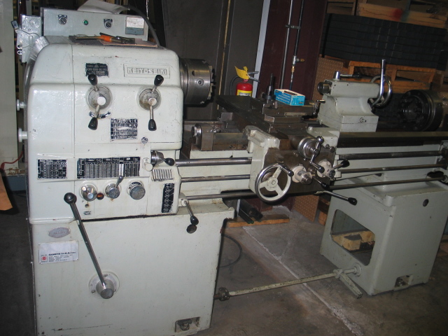
Keiyo Seiki KM-1800C
What a beauty – a 17×48 monster, even larger than the lathe I had used in class. With a 7.5HP motor, this beast should easily be able to chew through anything I dare to feed it. And a full quick change gearbox – no more messing with change gears or even belts for speed changes! The price was a steal at only $2100, and I knew that I better nab it now or live a life of regret. Of course, buying it and actually taking delivery are two very different things. I called Big Red Movers for a quote on actually moving it home, but they tossed out a price of $1000 for the service. Yeah, like I’m going to drop half the cost of the machine on just transporting it. A bit of chatting with coworkers finally hooked me up with someone with a truck and dump trailer who was able to help me haul it over to work. It was forklifted onto the trailer at the seller, and forklifted off the trailer at work, where I could temporarily store it while figuring out a way to transport it home.
I decided on building roller bases for the lathe in order to get it home and into the garage, as these had worked very well for my vertical mill. As long as the unit could be loaded onto a rollback tow truck, it could be rolled right off the truck bed (using the truck’s winch to gently lower it down the bed) into the garage. My dad managed to dig up most of the metal needed for building the roller bases, and I welded them up at work. I used the same Fairbanks swivel casters as I had on the mill bases, hoping that they’d be able to withstand the heavier load of the lathe. Once I had the bases built, I forklifted the lathe onto them, and wonder of wonders, they held. After that, it was a simple matter of hiring a rollback tow truck, rolling the lathe onto the bed (via the loading dock at work), and then bringing it home. I asked dad if he could help me with the unloading, as it makes me feel a lot better having someone around who has far more experience in such matters. Fortunately, the lathe came down the bed extremely smoothly, and we parked it neatly in the garage with a minimum of fuss. I’d deal with unloading it from the roller bases at a later time, but for now I could simply smile with satisfaction at finally having a ‘real’ lathe.
When you’re making aluminum parts for your own use, a raw ‘mill’ finish on the piece is just fine – why bother with making it more aesthetic when it’s just going to get dinged and dented as a result of simply being used? (Of course, once in a while I’ll feel a little creative and […]
When you’re making aluminum parts for your own use, a raw ‘mill’ finish on the piece is just fine – why bother with making it more aesthetic when it’s just going to get dinged and dented as a result of simply being used? (Of course, once in a while I’ll feel a little creative and impart a nice flycut finish on a part just for grins). But when you’re selling something that you’ve made, be it a paintball gun or a pizza cutter, the finish is often half of what the customer is looking at (sometimes even moreso – I’d wager that the modern consumer will almost always choose ‘shiny’ over ‘functional’). Metal finishing is thus a critical part of a product, and vibratory deburring/finishing is a common technique. It’s quite similar to the hobby rock tumbler kits you sometimes see – you have parts/rocks that get vibrated/tumbled around in a semi-abrasive media. This primarily knocks down burrs and takes the bite out of sharp edges, but it also helps provide an even finish to the large flat areas of a part. At any rate, it beats the heck out of hand polishing, which gets old really fast.
I started out with a Thumler’s Tumbler UV-18 and a Raytech starter kit of media. It worked great for small parts, but once I decided to try making aftermarket Phantom bodies, I knew I needed something larger. Of course, industrial sized vibratory finishers aren’t exactly cheap (the one Mike @ CCI uses for Phantom bodies is probably at least $6000), even when old beaters make a very rare appearance on craigslist. What do do? Make my own, of course.
The core of the unit would of course be the ‘tub’. I came across some mentions of people building their own massive tumblers by taking an old concrete mixer and spraying the inside with bedliner – a very novel approach, but was a little too large for my needs, and I wanted a vibratory unit rather than a tumbler, as I felt that a vibe unit would be gentler on the parts. I looked around at various rubbermaid type storage tubs, but worried about a rectangular tub having ‘dead zones’ that would get little movement, and having parts pooling up in those areas. I finally came across a post (which I’ve since lost the bookmark for) which had photos of a homebrew finisher – it was remarkably similar to the UV-18, but was simply scaled up in size. It used a car tire (on a rim) for a base, threaded rod and springs for a motor support system, and (most cleverly of all) laundry tubs for the tub. The clever part was that since the tubs nest for stacking, you can use a main tub for the housing, and simply drop in another tub to act as a replaceable liner. This made media changes very quick as well – just drop in the appropriate tub.
The one part of this design that seemed sub-optimal to me was the fact that the motor and tub had to be mounted on some sort of set of springs or grommets to keep the unit from vibrating all over the room. I wondered how much vibratory power that could be going into the parts/media was getting eaten up by the springs and grommets – the design is trying to create vibration in one part and eliminate it in another. In chatting with Lee about the project, it occurred to me that hanging the whole unit from the top rather than supporting it from underneath would be an ideal method to let all the motor power go into movement – no dampening would be needed, as everything could just precess around the single support point.
I found some laundry tubs at the hardware store, and not seeing any good motors on craigslist, I bought a 1/3 HP motor from Surplus Center. Turned out to be quite a beefy motor and certainly larger/heavier than I anticipated. But that’s rarely a bad thing – heavier stuff is generally better built (in fact, I’ve noticed on more than one occasion when disassembling a piece of electronic equipment that a lead or steel weight has been inserted into the unit simply to provide that feel of mass to fake out the user into thinking that the product is superior). I clamped a hunk of scrap aluminum to the shaft for the eccentric weight (which is actually what provides the vibration). As for hanging the complete unit, I considered building some sort of framework to suspend it (I had already ruled out hanging it from the basement rafters, as I had guessed that ‘sheer stupidity’ was not a valid clause in my homeowner’s insurance should the building suddenly collapse), then realized that ready made systems were already available as engine hoists. I decided that having an engine hoist around anyhow may not be a bad thing, and I found a used one on craigslist for a reasonable price.
Now that I had all the pieces, it was time to design. I used a copy of SolidWorks at work to first draw up one of the laundry tubs. I nested one inside another, slapped them onto a 12″x12″ steel plate, added in a rough model of the motor… …and just sort of ‘winged it’, much like building the enclosure for my Taig CNC. With the Speedy Metals catalog as a reference, I fleshed out the rest of the structure. An edrawing of the assembly is here.
CAD vision of the complete unit, minus chains
Once I had the design fleshed out, I ordered all the raw materials from Speedy Metals (sorry if it sounds like I’m just pimping them, but they’re a great place that doesn’t sneer at hobbyists). I still had to chain it all together, for which I used… chain. I picked up some cheap chain and the various other fasteners needed at another local hardware store (anyone not familiar with the glory that is Fleet Farm need only consult the Happy Schnapps Combo for further information). I milled simple slots in the ends of the upper bar (which was actually a length of galvanized perforated square tubing) so that the ends of a length of chain could be secured via a cross-bolt (which also held a hook in place, which would grab chain ‘straps’ from below, hoisting each end of the framework).
Chain connectionsThe full assembly, suspended via the engine hoist
For the deburring media itself, I’m currently using two different kinds:
Ceramic media - runs 'wet'Corn cob based polishing media - runs 'dry'
I also have a plastic based media, but it’s pretty slow to get results with. I’ll run parts in the ceramic media (with water and a bit of detergent) for a few hours, then put the parts in the corn cob based media and let that run overnight to shine up the pieces.
Everything works, but the parts don’t get deburred as fast as I’d like (though I’m pretty happy with the corn cob cycle). Even after clamping even more weight to the motor shaft, I’m not getting as much amplitude as I’d like – I’ve seen real industrial units, and they really get the media moving. Additionally, the ceramic media doesn’t ‘flow’ as well as in the little UV-18, and I get these ‘subduction zones’ in the media, where parts tend to pool. Using a bungee cord to pull the whole unit to the side and thus disrupt the circular symmetry seems to help a bit, but it’s far from perfect. I’m pretty sure I have enough motor power, and I’m wondering if I simply need to slow the speed down some, and/or have an even larger counterweight. I may need to rig up some sort of pulley system to allow for a larger counterweight and a way to adjust the speed of the weight rotation. I’m wondering if the ‘dead weight’ of the motor may be hurting things as well, especially since the motor is as the end of the ‘swing’ of the whole unit and effectively dampening vibration as a result (perhaps my brilliant idea of a suspended deburring system was not so brilliant after all). Eh, it still works, and saved me a heck of a lot of money, so I’ll consider it a success.
Rockerbox was this weekend and Chuck convinced me to head there with him. I was a little hesitant, having just a simple 2001 GS500, which is about as pedestrian as bikes get. Okay, the carbs are jetted, it has a Vance & Hines exhaust, Buell turn signals, etc., but I wouldn’t say it has the […]
Rockerbox was this weekend and Chuck convinced me to head there with him. I was a little hesitant, having just a simple 2001 GS500, which is about as pedestrian as bikes get. Okay, the carbs are jetted, it has a Vance & Hines exhaust, Buell turn signals, etc., but I wouldn’t say it has the ‘street cred’ of Chuck’s XJ550, which he equipped with white racing stripes for the event (looks really nice). Still, the event is essentially “if it’s 2 wheels, it’s cool”, so all was well.
We were hoping to meet up with Frankie and see the bike that he was working on for the event, but he emailed Chuck to say that he wasn’t going to complete it in time and would just be there with his Moto Guzzi (which I wanted to see just as badly). Apparently he made it, but we never collided with him. Still, we did find Steve, who we had met at the welding workshop, and he showed us the taillight unit that he had been working on in class for his BMW. Looked great on the bike, though it was mostly obscured by the tail fairing, so he also added LED flashers up top.
Walking around the contest area (where bikes are entered to win in categories from “Best European Modified” to “Worst Piece of Crap Award” is an amazing experience. Sure, I’ve seen episodes of American Chopper and the like where a custom bike is created, but the ones on display here were far more visceral and much more interesting. You really have to walk around a bike a few times to take in all the details of its execution.
This was one of my favorites - love the wrought iron footpegsThis bike is all attitude, and a deathtrap. Note the lack of a left handlebar.


