Chuck requested pics of the underside of the vibratory deburrer to show the counterweight. The underside actually doesn’t show very much, just the motor bolted flat to the lower plate: The real story is here, between the two plates: The counterweight started as just a hunk of aluminum, but in my quest to get more […]
Chuck requested pics of the underside of the vibratory deburrer to show the counterweight. The underside actually doesn’t show very much, just the motor bolted flat to the lower plate:
Boring the big hole through 1/4" steel plate wasn't exactly fun. Boring bars do NOT like interrupted cuts (I drilled a bunch of small holes through to knock out most of the material before switching to the boring head).
The real story is here, between the two plates:
Counterweight on the motor shaft
The counterweight started as just a hunk of aluminum, but in my quest to get more vibe out of the system, I bolted a hunk of stainless onto it as well. I’m thinking of switching to a belt driven counterweight of some sort so that I can have less wear and tear on the motor bearings and also vary the speed and amplitude of the vibration more easily.
Once I had the big Keiyo Seiki settled in place in the garage, attention turned to the question of “how the heck do I power this monstrosity”? For my Tree 2UVR vertical mill, I have a borrowed VFD (Variable Frequency Drive), which is able to transform the 240v single phase power (the same type of […]
Once I had the big Keiyo Seiki settled in place in the garage, attention turned to the question of “how the heck do I power this monstrosity”? For my Tree 2UVR vertical mill, I have a borrowed VFD (Variable Frequency Drive), which is able to transform the 240v single phase power (the same type of circuit a house would have for an oven, for example) into the 240v three phase power that the mill needs. It’s roughly analogous to the problem of powering a US intended appliance in the UK (120v versus 240v, respectively), only in this case additional power phases are needed. Three phase power is how electricity is actually generated and distributed as part of the electrical grid – when you look up at a large electrical tower, you’ll almost always see 3 wires (or a multiple of 3). These aren’t for the ground, neutral and ‘hot’ wires of a standard electrical outlet, but are rather the 3 phases of power generated by the utility. One of those phases gets split off and lowered in voltage through a variety of transformers to supply the 240v and 120v single phase power that your house uses.
The problem with single phase power in the case of machine tools is that it’s rather inefficient for electric motors, especially as the size of the motor increases. In addition, it adds to the cost and complexity of the motor. 3-phase motors on the other hand are simple, efficient, and (relatively) inexpensive, so they’re what industries use when a big-ass motor is called for. Of course, the local electric utility isn’t going to be terribly interested in running 3-phase power out to my garage just so I can run some beefy machine tools. As mentioned, I used a VFD on the mill, which is a completely solid state device that uses fancy electronics to create a 3-phase power output from a single phase power input (though using a 3-phase input is more common). Actually, the main use of a VFD is to be able to vary the motor’s speed (the ‘variable’ in VFD), hence why you’d want to have an input of 3-phase if you’re just going to turn it into a 3-phase output – you can run a standard 60Hz 3-phase motor at a crawling 20Hz or a blistering 200Hz (depending on how the motor is rated), but I had no use for this feature, as the mill has a variable speed head.
Getting a VFD large enough to power the lathe (a 7.5HP motor, versus only 1.5HP on the mill) would be terribly expensive, as I’d have to find a VFD of at least 10HP in capacity (most 3-phase VFDs can be run from single phase power, but they have to be derated). And if I wanted to power brake (kicking a forward rotating 3-phase motor into reverse electrically to slow/stop the motor more quickly), I’d worry about smoking the unit. The most cost effective way to power the lathe, I decided, would be to build a rotary phase converter (RPC).
The idea behind an RPC is simple and clever – you can actually run a 3-phase motor from single phase power, and when you do so, the unconnected leg of the motor will actually generate the third phase! By connecting the lines from this helper motor (called an ‘idler’, since the motor shaft doesn’t connect to anything, as the motor is used purely for its electrical characteristics and not for rotary mechanical power) to the motor of the machine you wish to use, you can power on the machine just as though it were connected to ‘real’ 3-phase power. To be nitpicky, the ‘fake’ 3-phase isn’t perfect (2 phases are 180 degrees apart rather than 120 degrees in a ‘real’ 3-phase system, and you have varying voltages on the 3 phases depending on load), but it’s ‘good enough’ for the majority of home shop applications.
I knew I needed a 10HP idler to power the 7.5HP lathe (I may have been able to get away with a 7.5HP idler, but it would probably have been marginal), so I started scouring various electrical suppliers, Surplus Center, etc. for a nice beefy TEFC (Totally Enclosed, Fan Cooled – a very rugged type of motor, with lots of thermal mass, making it good for RPCs). Not having much luck there, I turned to Ebay. Of course, I quickly realized I’d have to find something reasonably local, as the shipping charges for a 10HP motor are pretty hefty. I finally found one that looked to be perfect for my needs from a guy near Chicago. After chatting briefly over email with him about it, I decided to buy it. Turns out that the seller was Igor Chudov, whose RPC is actually the one shown on the Wikipedia page, and whose information on building RPCs I had stumbled across previously. I drove down to Chicago to pick up the motor in person, and Igor happily showed me his shop and the large dual idler RPC that he was currently using (he runs it with one idler motor spinning when he powers his mill or lathe, but kicks in the second idler if he needs to power his large air compressor). [edit – Igor helpfully corrected me, see comments. He does a staggered start on the idlers, but always runs both.] We managed to heft the motor into the truck, and I also bought a few other odds and ends that would be needed in the project – a motor starter (“big 3-phase relay”), a disconnect panel (“dangerous looking gray box with a big lever on the side”), and what the heck, I took a 7.5HP motor that he had as well.
10HP on left, 7.5HP on right10HP rating plate7.5HP rating plate
I’m not sure how I managed to actually get the 10HP motor out of the truck and into the garage by myself without requiring back surgery afterwards. You know something’s heavy when it has an eye bolt for lifting it. Before I could actually give it power, I needed to make sure that the garage wiring wouldn’t burst into flames. When I had first gotten the mill, I ran a 30 amp 240v circuit from the breaker box in the garage (my first attempt ever at running conduit, and it came out quite nicely). However, this wouldn’t suffice for running a max capacity of 17.5HP. I bought a 50 amp breaker and replaced the 10 gauge wiring on the circuit with 6 gauge wires for the split phases (the two ‘hot’ 240v wires) and an 8 gauge wire for the ground wire (this suggestion made by one of our EEs at work, who pointed out to me that the ground never carries current unless something goes really wrong, hence you can undersize the ground wire by a notch. This was needed because things were getting pretty tight in the conduit with 6 gauge wire. Pulling the wire through the conduit actually went really smoothly – the outer sheathing on the wire I bought at Home Depot is super slick and I was able to push it all the way through the conduit with no fish tape required. I topped it off with a beefy 3-pole outlet like we have at work for the welder outlet – looks nice and menacing and pretty much screams “don’t insert kitchen utensils here”.
If Chuck Norris was an electrical plug, he'd be this one.
With the facility wiring out of the way, I could finally try hooking up the 10HP monster and seeing if the blasted thing would spin. I took the disconnect box I bought from Igor and slapped a pair of 100 amp fuses into it (one fuse for each of the incoming lines). Really, I didn’t need fuses here at all – the breaker will pop way before the fuses go, but it was more expedient using ready-to-go fuses than trying to find some copper plate to use in their place. I then ran wires from the bottom of the disconnect panel to the 10HP motor – 2 ‘hot’ wires and one ground, with the third phase on the motor left unattached to anything. I used wire nuts for the actual wire attachment and electrical tape to cover up any scary looking bare conductors. I then ran a cable off the top (input) of the disconnect panel and connected it to a 3-pole plug suitable for insertion into the 50 amp outlet. The disconnect panel is basically just a switch. A really big, mean, nasty, mad-scientist movie type of switch, reminiscent of the giant knife switches you’d see in Frankenstein’s lab. The lever on the side actually takes a bit of force to move between ‘on’ and ‘off’, and it makes a satisfying ‘ka-chunk’ when toggled. This ain’t no lightswitch, kids.
Disconnect panel exteriorInside the disconnect panel - the three hook shaped contacts to the left of the fuses rotate downwards to complete the circuit as the lever is switched into the 'on' position
The scary part of testing the 10HP motor wasn’t just that I had to apply 50 amps of circuit juice to the beast, it was that I had to apply power with the motor spinning. You see, once a 3-phase motor is spinning under proper 3-phase power, you can disconnect one of the phases and have it still run (known as ‘single-phasing’, which is generally not desirable, as voltages start getting wonky). But you can’t apply single phase power to a stationary 3-phase motor and have it magically spin up – this requires special capacitors, which I did not have. What’s needed is a ‘pony motor’ (usually just a small 120v single phase motor) that you can couple temporarily to the idler to get it spinning, then pull away the pony motor and apply single phase power to the idler. Of course, then I’d have to wire up another blasted motor and figure out how to couple it to the idler and… Well, there is of course a simpler solution, which starts getting into ‘horrible kludge’ territory – use a pull cord of some sort wrapped around the idler motor shaft. I used the end of a tie-down strap, and wound it around the motor shaft about a dozen times (motor bearings were really nice and smooth, I noted – certainly a good sign). I plugged the power cable from the disconnect box into the wall outlet and flipped on the breaker. All that remained was to give the strap a smooth, forceful pull, then quickly flip the disconnect lever upward to apply power. Everything I read said it should work, yet looking at those big copper wires still gives one pause – a healthy respect for electricity does tend to keep one alive, after all. I grabbed onto the strap and… had a second thought and rummaged around for my safety glasses.
Eye protection in place for any mishaps (note to self – buy fire extinguisher for the garage), I yanked the strap, tossed it behind me (loose straps and spinning shafts are not a good combo) and shoved the disconnect lever upwards to ‘on’. The motor kept going, but it didn’t appear happy, making a disconcerting waohwaohwaohwaohwaoh noise, and it looked like the shaft wasn’t spinning nearly as fast as it should. I stared at it in puzzlement for a few moments before hearing a ‘clack’ from the breaker panel. Tripping the breaker meant it had certainly been drawing more current than it should have, and I wondered if perhaps I didn’t have it spinning fast enough. After allowing a few minutes for the breaker to cool off, I wrapped the strap around the motor shaft once more and gave it a more forceful pull this time, getting it to a faster speed before applying power at the disconnect. This time the motor happily revved up to its rated speed, emitting only a quiet, gentle hum that belied the massive power that it was capable of.
Next of course would be the real test – hooking the lathe up to the idler and seeing if I could get the lathe spinning. This was pretty simple – just attaching a few more wires. Once I had the idler spinning and powered again, I turned on the disconnect on the lathe, switched the power to ‘on’, made sure I didn’t have the carriage or cross-slide in feed mode, and moved the lathe’s control level to ‘forward’. The contactors in the lathe’s power panel clattered and buzzed as the ammeter on the panel jumped around on the far end, attesting to the volume of electrons tearing through the system. The giant chuck began turning, and the clatter died down, leaving only the whirr of properly meshing gears and the low growl of the machine’s motor. Yes, it was alive.
It’s a pretty sure sign that you’re a machine tool junkie when you browse through the craigslist ads, see a machine that you have no room for, no acceptable source of AC power for, and no conceivable need for, but you still check the balance in your checking account. Such was the case the other […]
It’s a pretty sure sign that you’re a machine tool junkie when you browse through the craigslist ads, see a machine that you have no room for, no acceptable source of AC power for, and no conceivable need for, but you still check the balance in your checking account. Such was the case the other week when I saw a Sunnen LB hone for only $250. I have no immediate need for one, though there are a few projects in mind where it would be useful. There’s hardly any info on them available (entering ‘sunnen model lb hone’ into google yielded as the first result… …that very craigslist ad), and this one was in need of new belts at a minimum (I had stopped by to have a look at the unit, being only 5 minutes away from work). Still, after pondering it overnight, I left a voicemail for the seller the next day telling him I’d take it. I got a voicemail back informing me that it had already been sold. Phew, what a relief!
I have a number of machines currently in my possession, though in this post I’ll just talk about the lathes, as the newest one is the source of most monetary expenditures as of late. A puny little Grizzly 7×10 lathe was my first machine tool purchase many years ago, and it was so small that it’s not even offered anymore, having been replaced by the 7×12. For those unfamiliar with machine tool lingo, calling a lathe a “7×10” or a “12×36” is roughly analogous to calling an engine a “305 cubic inch”, as the ‘displacement’ is essentially what is being described – the first number refers to the size of the largest diameter part that the lathe can hold, and the second number refers to the longest length part that can be turned ‘between centers’, which is a common method of workholding. In the case of the 7×10, it could work with a short stubby piece of 7″ in diameter, or a long thin piece of 10″ in length, hence the 7×10 designation. It wasn’t a great lathe, but it had all the features I wanted, especially the ability to cut threads. I knew I’d probably wind up getting a larger unit someday, but this one sufficed just fine as a ‘trainer’ model.
The poor little 7x10 now sits unused under piles of debris in the garage
Sure enough, many years later I really needed an upgrade, as the little 7×10 just didn’t have the torque, rigidity, or capacity that I needed. Plus, having to swap gears (plastic ones, no less) to change thread pitches was a pain. I eventually worked out a trade with Doc Nickel, who was also on the upgrade path – I had a bunch of solenoid valves, and he had a Grizzly 9×20 that he had outgrown. It was just the thing I had been looking for, and it certainly had a bit of history behind it, having modified countless paintball guns into custom works of art. Of course, I then wanted to modify the machine after a time, and I decided to replace the 3-jaw chuck with a 5C collet chuck for improved workholding on round pieces (getting a good grip on parts with a 3-jaw chuck generally leaves unsightly dents in the part where the jaws have dug in). Not being exactly sure of what mounting system I needed for the chuck, I called New England Brass & Tool, and Bob Cumings made certain to get me just what I needed, even throwing in a depth stop as a freebie, as he knew I’d find it useful. The 5C was indeed a great addition, and in fact I never took it off.
The 9x20, with 5C collet chuck and quick change toolpost
While that was all well and good for workholding, the toolholding still needed attention – like the 7×10, the 9×20 had only a turret style toolpost. Not that a turret toolpost isn’t bad, but the stock toolposts on these little import lathes simply aren’t very good – they’re poor imitations of ‘real’ turret toolposts, and are used simply because they’re inexpensive to manufacture. I bought a Phase II piston-style quick change tool post, which, as the name implies, allows for quick changes of tools, each held securely in its own dovetailed toolholder. Additionally, I removed the compound from the lathe entirely, as they are not particularly rigid on these lathes, and I couldn’t forsee turning many tapers. Instead, I mounted the toolpost to a thick aluminum plate which itself got bolted to the cross-slide (which thankfully has T-slots perfect for this). This served me well for quite some time, but of course it couldn’t last. Once I moved up to a full size vertical mill I naturally needed a lathe to match, especially after taking a lathe class at MATC – after using a Summit 18×40 for a semester, I could barely even look at my feeble 9×20. (Not to mention that the class lathes were outfitted with DROs, Aloris (real Aloris, mind you) wedge style quick change tool posts and a full complement of Kennametal tooling)
I first had my eye on a used Jet 14×40 at a local machine tool dealer – it needed some parts, but it had a big 3″ bore through the headstock. The dealer wanted $3000 for it, and I figured I could save up the cash for it. Naturally, though, someone swooped in and bought it. I then had my eye on a nice big Andrychow TUG-40 from the same dealer – certainly a nicer, bigger lathe, but with a pricetag to match – something like $5700. Ouch. I figured I’d have to make acquiring a big lathe a much longer term project. I browsed craigslist for months on end, hoping to find just the right one at a price that wouldn’t kill me. Then, in January, I found the one I had been waiting for.
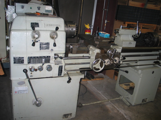
Keiyo Seiki KM-1800C
What a beauty – a 17×48 monster, even larger than the lathe I had used in class. With a 7.5HP motor, this beast should easily be able to chew through anything I dare to feed it. And a full quick change gearbox – no more messing with change gears or even belts for speed changes! The price was a steal at only $2100, and I knew that I better nab it now or live a life of regret. Of course, buying it and actually taking delivery are two very different things. I called Big Red Movers for a quote on actually moving it home, but they tossed out a price of $1000 for the service. Yeah, like I’m going to drop half the cost of the machine on just transporting it. A bit of chatting with coworkers finally hooked me up with someone with a truck and dump trailer who was able to help me haul it over to work. It was forklifted onto the trailer at the seller, and forklifted off the trailer at work, where I could temporarily store it while figuring out a way to transport it home.
I decided on building roller bases for the lathe in order to get it home and into the garage, as these had worked very well for my vertical mill. As long as the unit could be loaded onto a rollback tow truck, it could be rolled right off the truck bed (using the truck’s winch to gently lower it down the bed) into the garage. My dad managed to dig up most of the metal needed for building the roller bases, and I welded them up at work. I used the same Fairbanks swivel casters as I had on the mill bases, hoping that they’d be able to withstand the heavier load of the lathe. Once I had the bases built, I forklifted the lathe onto them, and wonder of wonders, they held. After that, it was a simple matter of hiring a rollback tow truck, rolling the lathe onto the bed (via the loading dock at work), and then bringing it home. I asked dad if he could help me with the unloading, as it makes me feel a lot better having someone around who has far more experience in such matters. Fortunately, the lathe came down the bed extremely smoothly, and we parked it neatly in the garage with a minimum of fuss. I’d deal with unloading it from the roller bases at a later time, but for now I could simply smile with satisfaction at finally having a ‘real’ lathe.
When you’re making aluminum parts for your own use, a raw ‘mill’ finish on the piece is just fine – why bother with making it more aesthetic when it’s just going to get dinged and dented as a result of simply being used? (Of course, once in a while I’ll feel a little creative and […]
When you’re making aluminum parts for your own use, a raw ‘mill’ finish on the piece is just fine – why bother with making it more aesthetic when it’s just going to get dinged and dented as a result of simply being used? (Of course, once in a while I’ll feel a little creative and impart a nice flycut finish on a part just for grins). But when you’re selling something that you’ve made, be it a paintball gun or a pizza cutter, the finish is often half of what the customer is looking at (sometimes even moreso – I’d wager that the modern consumer will almost always choose ‘shiny’ over ‘functional’). Metal finishing is thus a critical part of a product, and vibratory deburring/finishing is a common technique. It’s quite similar to the hobby rock tumbler kits you sometimes see – you have parts/rocks that get vibrated/tumbled around in a semi-abrasive media. This primarily knocks down burrs and takes the bite out of sharp edges, but it also helps provide an even finish to the large flat areas of a part. At any rate, it beats the heck out of hand polishing, which gets old really fast.
I started out with a Thumler’s Tumbler UV-18 and a Raytech starter kit of media. It worked great for small parts, but once I decided to try making aftermarket Phantom bodies, I knew I needed something larger. Of course, industrial sized vibratory finishers aren’t exactly cheap (the one Mike @ CCI uses for Phantom bodies is probably at least $6000), even when old beaters make a very rare appearance on craigslist. What do do? Make my own, of course.
The core of the unit would of course be the ‘tub’. I came across some mentions of people building their own massive tumblers by taking an old concrete mixer and spraying the inside with bedliner – a very novel approach, but was a little too large for my needs, and I wanted a vibratory unit rather than a tumbler, as I felt that a vibe unit would be gentler on the parts. I looked around at various rubbermaid type storage tubs, but worried about a rectangular tub having ‘dead zones’ that would get little movement, and having parts pooling up in those areas. I finally came across a post (which I’ve since lost the bookmark for) which had photos of a homebrew finisher – it was remarkably similar to the UV-18, but was simply scaled up in size. It used a car tire (on a rim) for a base, threaded rod and springs for a motor support system, and (most cleverly of all) laundry tubs for the tub. The clever part was that since the tubs nest for stacking, you can use a main tub for the housing, and simply drop in another tub to act as a replaceable liner. This made media changes very quick as well – just drop in the appropriate tub.
The one part of this design that seemed sub-optimal to me was the fact that the motor and tub had to be mounted on some sort of set of springs or grommets to keep the unit from vibrating all over the room. I wondered how much vibratory power that could be going into the parts/media was getting eaten up by the springs and grommets – the design is trying to create vibration in one part and eliminate it in another. In chatting with Lee about the project, it occurred to me that hanging the whole unit from the top rather than supporting it from underneath would be an ideal method to let all the motor power go into movement – no dampening would be needed, as everything could just precess around the single support point.
I found some laundry tubs at the hardware store, and not seeing any good motors on craigslist, I bought a 1/3 HP motor from Surplus Center. Turned out to be quite a beefy motor and certainly larger/heavier than I anticipated. But that’s rarely a bad thing – heavier stuff is generally better built (in fact, I’ve noticed on more than one occasion when disassembling a piece of electronic equipment that a lead or steel weight has been inserted into the unit simply to provide that feel of mass to fake out the user into thinking that the product is superior). I clamped a hunk of scrap aluminum to the shaft for the eccentric weight (which is actually what provides the vibration). As for hanging the complete unit, I considered building some sort of framework to suspend it (I had already ruled out hanging it from the basement rafters, as I had guessed that ‘sheer stupidity’ was not a valid clause in my homeowner’s insurance should the building suddenly collapse), then realized that ready made systems were already available as engine hoists. I decided that having an engine hoist around anyhow may not be a bad thing, and I found a used one on craigslist for a reasonable price.
Now that I had all the pieces, it was time to design. I used a copy of SolidWorks at work to first draw up one of the laundry tubs. I nested one inside another, slapped them onto a 12″x12″ steel plate, added in a rough model of the motor… …and just sort of ‘winged it’, much like building the enclosure for my Taig CNC. With the Speedy Metals catalog as a reference, I fleshed out the rest of the structure. An edrawing of the assembly is here.
CAD vision of the complete unit, minus chains
Once I had the design fleshed out, I ordered all the raw materials from Speedy Metals (sorry if it sounds like I’m just pimping them, but they’re a great place that doesn’t sneer at hobbyists). I still had to chain it all together, for which I used… chain. I picked up some cheap chain and the various other fasteners needed at another local hardware store (anyone not familiar with the glory that is Fleet Farm need only consult the Happy Schnapps Combo for further information). I milled simple slots in the ends of the upper bar (which was actually a length of galvanized perforated square tubing) so that the ends of a length of chain could be secured via a cross-bolt (which also held a hook in place, which would grab chain ‘straps’ from below, hoisting each end of the framework).
Chain connectionsThe full assembly, suspended via the engine hoist
For the deburring media itself, I’m currently using two different kinds:
Ceramic media - runs 'wet'Corn cob based polishing media - runs 'dry'
I also have a plastic based media, but it’s pretty slow to get results with. I’ll run parts in the ceramic media (with water and a bit of detergent) for a few hours, then put the parts in the corn cob based media and let that run overnight to shine up the pieces.
Everything works, but the parts don’t get deburred as fast as I’d like (though I’m pretty happy with the corn cob cycle). Even after clamping even more weight to the motor shaft, I’m not getting as much amplitude as I’d like – I’ve seen real industrial units, and they really get the media moving. Additionally, the ceramic media doesn’t ‘flow’ as well as in the little UV-18, and I get these ‘subduction zones’ in the media, where parts tend to pool. Using a bungee cord to pull the whole unit to the side and thus disrupt the circular symmetry seems to help a bit, but it’s far from perfect. I’m pretty sure I have enough motor power, and I’m wondering if I simply need to slow the speed down some, and/or have an even larger counterweight. I may need to rig up some sort of pulley system to allow for a larger counterweight and a way to adjust the speed of the weight rotation. I’m wondering if the ‘dead weight’ of the motor may be hurting things as well, especially since the motor is as the end of the ‘swing’ of the whole unit and effectively dampening vibration as a result (perhaps my brilliant idea of a suspended deburring system was not so brilliant after all). Eh, it still works, and saved me a heck of a lot of money, so I’ll consider it a success.
Soldering Class I’ve done a lot of electronics soldering before, but jewelry soldering is a completely different animal. Temperatures are much higher (we used oxyacetylene torches) and the solder is much stronger. Fluxing is extremely important, but what really floored me was the minuscule amount of solder ideally used – this isn’t like soldering copper […]
Soldering Class
I’ve done a lot of electronics soldering before, but jewelry soldering is a completely different animal. Temperatures are much higher (we used oxyacetylene torches) and the solder is much stronger. Fluxing is extremely important, but what really floored me was the minuscule amount of solder ideally used – this isn’t like soldering copper water pipes, where you smear some flux on, heat up the joint and feed the solder wire into the junction. Instead, you clip off teeny little 1/32″ sized pieces of solder from the already small gauge (and surprisingly stiff) solder wire and delicately arrange them along the solder joint (which should itself be as close and tight fitting as possible), using the flux to hopefully keep them in place while torching the whole mess.
First two soldering pieces
These were the first two joint types we started out on – a post on a surface and a right angle. Only a single little piece of solder was needed for the post, and the right angle used little pieces spaced at about 1/4″ intervals along the joint.
Right angle and butt joints
I placed the solder on the inside of the right angle joint, so the outside has a nice, clean, thin line of solder. I’d then sand down the little bit that stuck out if I was making a finished piece. The butt joint piece is a copper/brass sandwich that I started sanding down the surfaces on (Chuck went nuts on the piece that he did and basically had a mirror finish after a great deal of sanding and buffing – absolutely no solder was visible when he was done).
There was another piece that we were to try – a hemispherical piece attached to a plate (basically just a bump) which used the clever technique of applying white-out to keep the solder from running (yellow ochre can also be used). Like all the other examples, Frankie made it look easy. I managed to blacken the part into oblivion with no adhesion whatsoever. So I hid the evidence and moved onto trying to make a ring (the intended end product of the class, after all).
Copper rings
My first attempt at a copper ring (on the left) was, well, an attempt. Two little blobs of solder looked to be very weakly holding the ends together, so I thought I’d just pop them apart by smacking a dapping tool through the ring. No such luck – though those little solder bits may appear feeble, they are strong. I opted to just start over and fluxed the next joint a little more carefully and applied a bit more solder as well. The resulting ring (on the right) was far better, and I was quite satisfied with what I had learned (not even having touched the sterling silver pieces we were given for making our final rings).
Welding Class
For the welding class, we were to make either a vessel or a sculpture. Chuck immediately thought of trying to do something with the gas tank on his bike, but not having been struck with the urge to modify the tank on my GS500, I looked around for what the heck I could try to make. I finally hit upon a gas can, as it was small enough that I could make it from the allotted sheet of steel.
Gas can and resulting templates
I laid some newspaper down on the gas can and then wrapped the whole thing in masking tape. I then sliced the tape/paper layer off along what I felt were reasonable edges and make cardboard templates. After tracing the templates onto the sheet metal, I then cut out the pieces.
Forming the bottom
I started with the bottom piece, as I was eager to try hammering on the shot bag. You can’t just bash away at the metal as a release of pent-up aggression, but rather you have to carefully sculpt it. Notice the notches I made in the template at the corners – I found these weren’t nearly big enough to allow the corners to bend as much as needed, and I kept having to open them up further and further. Naturally I went too far eventually, and quickly realized that this was far too ambitious a project for a 3 night class, not to mention being a raw beginner.
Other sections of the intended gas can
With this realization, I decided to skip trying to actually join these parts together into a cohesive unit and simply toyed with running them through the English wheel, planishing hammer, shrinker and stretcher to understand how to use those tools to shape the metal.
Technically, it's a vessel
I backtracked a bit and decided to try something much more prismatic and simple. I figured I’d roll a sheet into a cylinder and cap one end with a plate to get something roughly cup-like. Of course, I then decided to make things a little more complex by going for a cone rather than a cylinder, but it was still simple enough to be successful. Successful in shaping it, at any rate. MIG welding sheet metal is a tricky process, I quickly found – blowing right through a hot joint is all too easy, and I started wishing for a TIG torch (not that it would have done me much good – I’m still an amateur on TIG, but I did miss the extra control that it gives on delicate pieces). Once I had finished the vessel into something that wouldn’t leakwouldn’t break apart when I dropped it would stand stably on a table without falling over, I called it a night and just watched Chuck while he worked on his tank decorations.
Open Workshop
The last session was basically an open session for people to work on things from other classes. Chuck worked on a bit of soldering and powdercoating, and I thought I’d give anodizing a go, as it consisted of a good deal of waiting (the Thunderbirds were in town for the airshow and I was rather distracted by the sight of aircraft flying around outside). The first piece I tried was an ‘oops’ Roundhead body that I had brought along (it had shifted while machining, making it unsuitable for actual use). It had been freshly tumbled with ceramic media in the vibe deburrer (which will itself hopefully be the subject of a future post), and I wanted to see what sort of anno could be had with it. Frankie helped me wire it up and clean it, and then we let it sit in the anno bath for 45 minutes while I alternated between looking out the window for airplanes, trying to find airshow traffic on my scanner radio, and annoying Chuck. After the anno bath, I elected to try a dye labeled ‘Fiery Red’ for a color, which turned out to be a really nice shade. Once the dye was sealed, the finish on the piece was slightly dull, but I expected this, as you simply can’t get the really shiny finishes without an electropolish or bright dip (both well outside the means of a hobbyist sized anno operation). Frankie suggested giving it a coat of wax, so I used a bit of Renaissance Wax on the surface. After buffing it off, I’d be hard pressed to tell it apart from a commercial bright dip anno.
Anno pieces
I also tried another piece that I applied a hammered finish to (using a cross pein hammer). I really like the look of this finish and am pondering doing a Phantom in this hammered pattern over the entire surface.
My very first summer job was working at the local trophy shop, where we had several computerized engravers. As it turns out, they were extremely similar to the Taig CNC mill that I would many years later acquire – driven by steppers in the X and Y axes and controlled via a desktop PC, it’s […]
My very first summer job was working at the local trophy shop, where we had several computerized engravers. As it turns out, they were extremely similar to the Taig CNC mill that I would many years later acquire – driven by steppers in the X and Y axes and controlled via a desktop PC, it’s really not a stretch to consider them specialized CNC tools. Our most commonly used engraver was a ‘diamond drag’ type, which essentially used a diamond tipped tool to scratch through the lacquer covering a sheet of brass or aluminum (our other engraver used a rotary cutter for engraving on plastics).
Once I had my Taig, I realized I could certainly do a little engraving myself, I just needed the right tool. On the engraver at the trophy shop, the ‘head’ was actually pneumatic – rather than a Z axis, there was simply a 3-way solenoid valve that would apply air to a spring retracted engraver. More air pressure meant deeper engraving. There had been plans in Home Shop Machinist (might have been the sister publication, Machinist’s Workshop) for a spring-loaded engraver for use on CNC mills a while back, but I wasn’t thrilled with the design – not only did it reduce the working travel in Z, but had to go in the spindle. I wanted an engraver that could be attached to the side of the headstock (Taig headstocks have T-slots for such purposes) which would not only be a bit more rigid, but would allow me to machine a shallow flat on a part and immediately engrave in that area without any tool changes.
Construction is simple – the only purchased parts were the diamond drag engraver (I used a DG-250 from Antares), a pair of clamp collars, and a spring. The body was a hunk of scrap extrusion from work – it had a 5/16″ hole already down the length of it. I machined a pair of bushings from some Oilite bronze rod stock and pressed them into each end of the body (I had bored each end out a little bit). Though I had reamed the bushings to have a 1/4″ hole through them, there was enough axial misalignment between the two to cause the engraver to bind when I tried to run it through. So I tried something a little crazy – I chucked a long piece of 1/4″ drill rod in the lathe, lightly scuffed the last two inches or so of the rod with a diamond hone, slathered it in oil, and ran it through the bushings. This trued things up just enough to allow the engraver to slide through the bushings freely, but with zero side play. A bit of strip steel, some threaded rod and wingnuts, and it’s ready to attach.
Last month Chuck forwarded me an innocuous sounding email from the local vintage motorcycle mailing list. There were a few metalworking classes being held at the art school at UWM, and he was thinking of signing up for a few. They did sound intriguing, and I figured I’d tag along with him for the soldering […]
Last month Chuck forwarded me an innocuous sounding email from the local vintage motorcycle mailing list. There were a few metalworking classes being held at the art school at UWM, and he was thinking of signing up for a few. They did sound intriguing, and I figured I’d tag along with him for the soldering and welding classes (I had taken TIG and stick welding classes before, but welding/forming sheet metal was new to me, and I really wanted to learn soldering techniques for when I eventually try tinkering around with brass paintguns). The emphasis on hand work both intimidated and excited me – I’m used to the sharp, prismatic capabilities of mills and lathes, and the ability to create free-flowing shapes without use of CNC is a skill that I covet and admire.
Being that the classes were run through the art school, I was a little apprehensive – I’ve never really ‘gotten’ fine art, though I have certainly tried. I did take an art history class as an elective long ago, and though I did come away with an appreciation for the intent of the Dadaists and marveled at the technical skill of the Trompe-l’œil painters, I just can’t get past the attitude that seems part and parcel of ‘art’ – the feeling that ‘art’ is more and more meant only to be consumed by others in the field, removing it from the reach of the common person. I checked out a DVD of Chihuly Over Venice at the library a while back, as glassblowing certainly takes a great deal of skill and I wanted to learn more about the craft. However, the video was disappointing – Dale Chihuly struts around the whole time, commanding other glass blowers in what to do, and the end result is a bunch of twisted orange glass hanging from some steel pipes that he had no hand in the actual making of. I wanted to see more of what the craftsmen were doing, as they should be given the credit for creation. It basically reinforced my appraisal that to be an artist requires only two things: a beret and an attitude. (Addendum – I’ve since found that Chihuly had suffered a shoulder injury some time back that left him unable to continue doing his own glasswork, thus he relies on other craftsmen. I have to give him a pass on that account, but I still don’t get his art.)
Still, the fact that our instructor, Frankie Flood, had an interest in motorcycles and had made motorcycle themed pizza cutters (which I actually remember seeing on a number of blogs last year, and could actually appreciate as artistic objects), I had hope that I could learn some new skills rather than simply be baffled by ‘art’. I was not disappointed. Class ran from 6pm to 9pm, though Chuck and I invariably stayed long after to chat extensively with Frankie over the widest range of topics imaginable, from machining techniques, to educational systems, to the philosophy of craftsmanship (we’ve all bought copies of Shop Class as Soulcraft). Refreshingly, even though Frankie was art department faculty, he had the same difficulty of wrestling with ‘art’ that I have had. When he elected to build a chopper for his thesis, his professors were abhorred, decreeing such work as lowbrow and worthless (wonder if they said the same of Roy Lichtenstein). He still struggles with this, noting that ‘art’ has become more about the ‘idea’ rather than the craft. It all leads me to wonder – maybe I won’t be able to ever understand ‘art’, but with artists and teachers like Frankie out there, maybe someday ‘art’ will understand us.
I’ve been working on cocker threaded Phantom bodies for quite some time, and the latest incarnation is a ‘full round’ version. I had a job shop do the internal machine work on them as I didn’t yet have the big lathe running (which I’m now having some regrets on – the cost was substantial, it […]
I’ve been working on cocker threaded Phantom bodies for quite some time, and the latest incarnation is a ‘full round’ version. I had a job shop do the internal machine work on them as I didn’t yet have the big lathe running (which I’m now having some regrets on – the cost was substantial, it took over 5 months, and despite what I was told at first, they want the invoice paid in full NOW). I wanted to do the final machining in a single setup, as they’re round and alignment would be a concern were I to try multiple setups. Furtheremore, a single setup would require 4th axis operation, as there are features on the top and bottom of the part. In short, there were a lot of ‘firsts’ for me in this project, and it’s the most ambitious CNC program I’ve yet done (experienced CNC machinists would laugh at its simplicity, but hey, I’m learning).
Detent slot milling operation in progress
I broke the program down into pieces, some of which I had already done. There are 5 subroutines in use:
sear slot
threaded insert counterbore
feed port
threadmilling for insert counterbore
detent slotting
The sear slot is first, then the underside counterbore, rotate 180 degrees, then the topside counterbore and feed port. Tool is changed to the threadmill, top counterbore is threaded, rotate 180 degrees and thread the bottom counterbore. Finally switch to the ball end mill and run the detent slots. Total run time is still over a half hour, which I hope to cut down a bit by removing some unneeded ‘air’ cuts, increasing feeds, etc. Still, the satisfaction is immense – I’ve had a lot of tools (the 4th axis, tooling plate, tailstock, bullnose live center, etc.) sitting idle for a very long time (they were all purchased with this project in mind), and it’s a great feeling to finally have them put to use.
Mach3 while running the CNC programThe three tools used in the program, held in A2Z endmill holders


